
Phase discrimination for micro electrical measurement in non-conductive fluid

a non-conductive fluid and phase discrimination technology, applied in the direction of instruments, measurement devices, seismology, etc., can solve the problems of obscuring the formation signal, causing errors in voltage measurement, and poor and unusable signals between the pad and the wellbore wall

Inactive Publication Date: 2005-08-18
SCHLUMBERGER TECH CORP
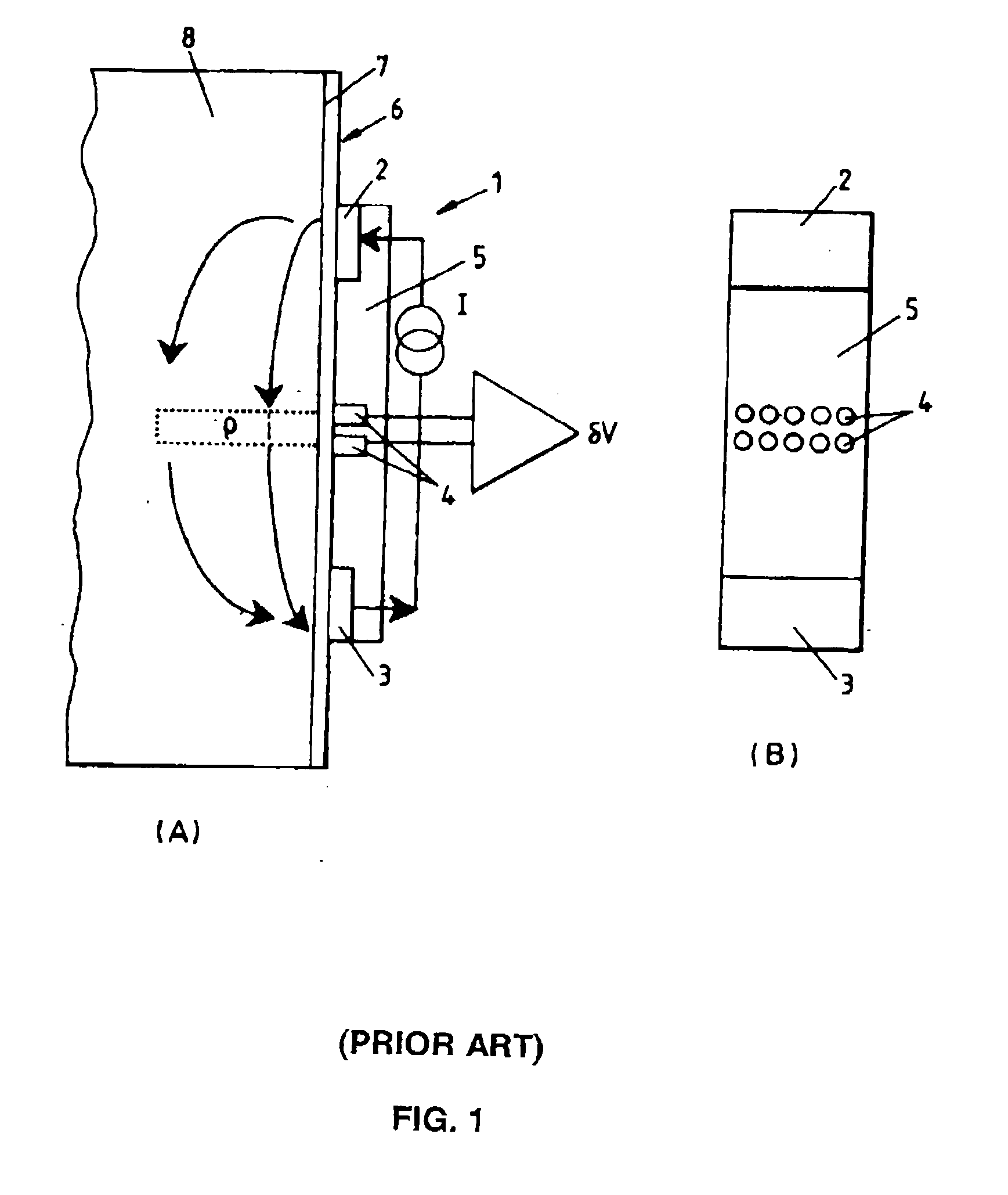
View PDF8 Cites 53 Cited by
  • Summary
  • Abstract
  • Description
  • Claims
  • Application Information

AI Technical Summary

Benefits of technology

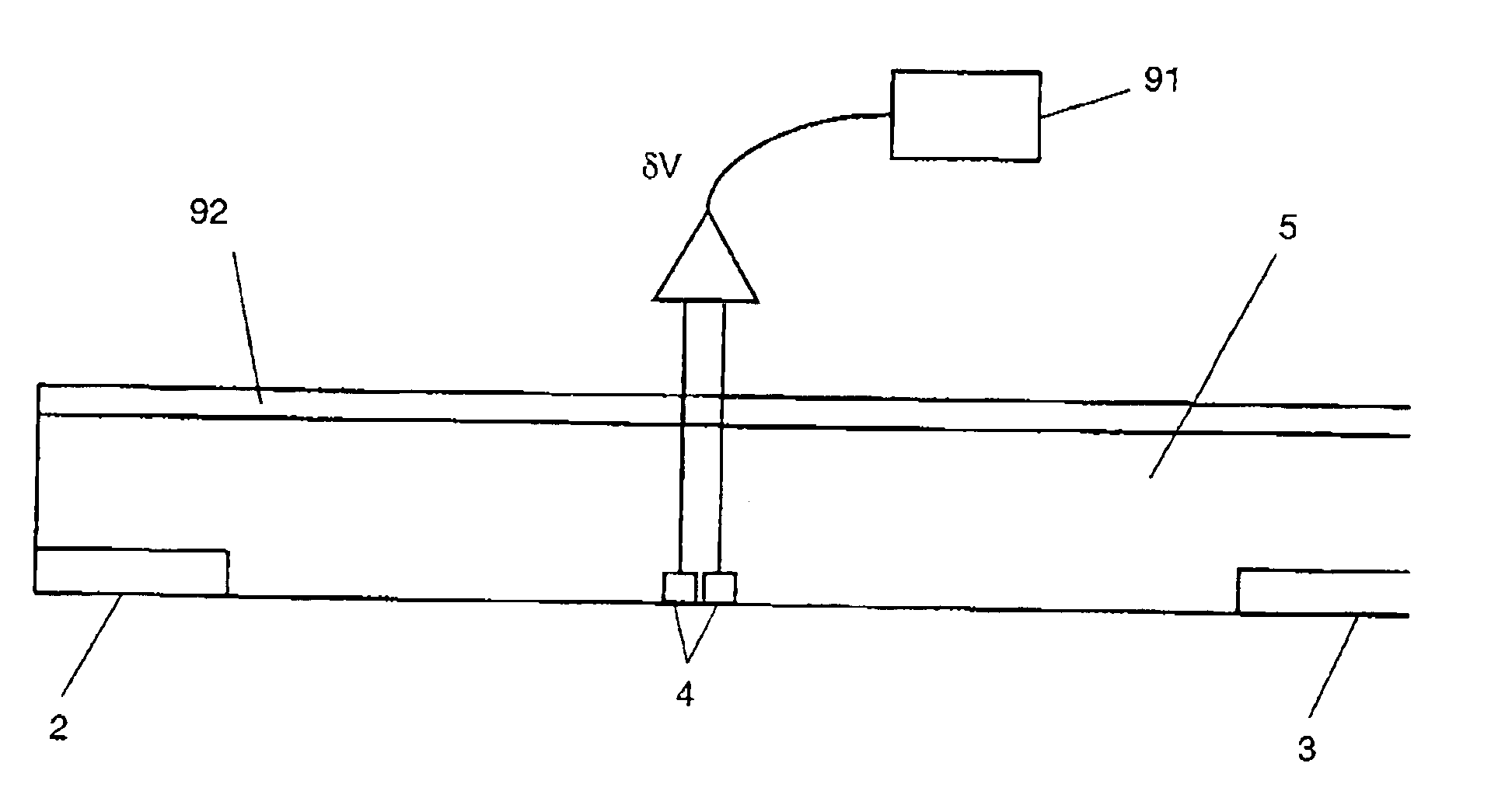
The invention is a method for electrically investigating a wall borehole in a geological formation by injecting a current and measuring the voltage between two positions on the wall. The method includes measuring the voltage between a third and fourth position that are located between the first and second positions. The invention also includes calculating the formation resistivity based on the current and the component of the voltage in phase with the current. The well-logging tool according to the invention includes a pad, a source electrode, a return electrode, an ammeter, at least one pair of voltage electrodes, and a phase sensitive detector. The pad is placed into contact with the wall of a borehole and the conductive back plate is on the back face of the pad. The technical effects of the invention include improved accuracy in measuring the resistivity of geological formations and improved accuracy in detecting the location of leaks in wellbores.

Problems solved by technology

If, however, a non-conductive drilling fluid (“mud”) is used, such as an oil based mud or water-in-oil emulsion type mud, the resulting non-conductive mud layer between the pad and the wellbore wall produces poor and unusable signals.
Errors in the voltage measurement occur because the voltage electrodes 4 couple not only to the formation but also to the conductive backplate.
The scalar corrected resistivity curves in the two formations are more accurate in the range from no standoff to the point on each curve where the mud signal becomes dominant, but at large standoff the mud signal overwhelms the formation signal and the data are unusable.

Method used


Image

  • Phase discrimination for micro electrical measurement in non-conductive fluid
  • Phase discrimination for micro electrical measurement in non-conductive fluid
  • Phase discrimination for micro electrical measurement in non-conductive fluid

Examples


Embodiment Construction

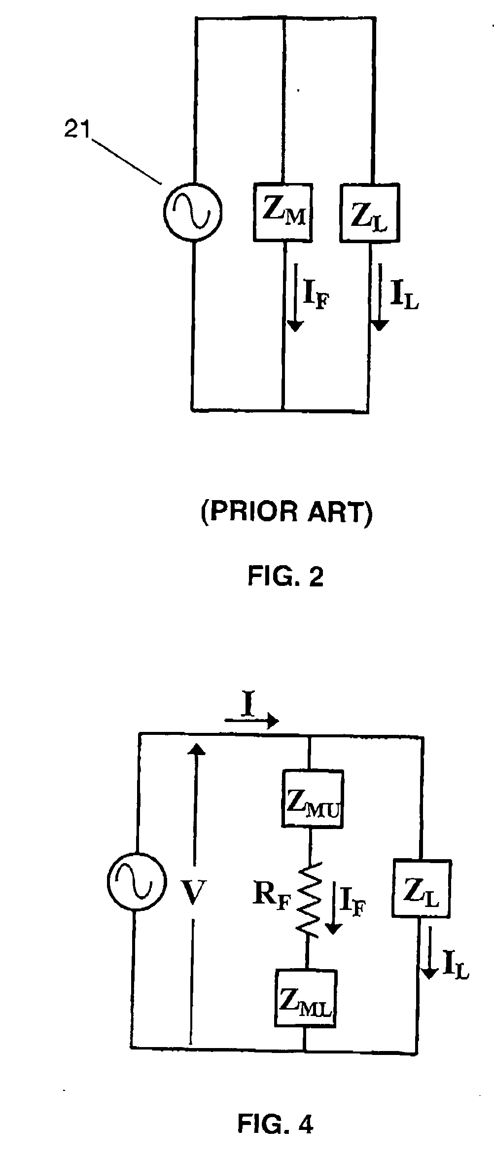
[0034] The present invention includes a new method and apparatus for discriminating against unwanted signals when making microeletric investigations of a borehole wall. The invention is based on the electric properties exhibited by the materials near the voltage electrodes, when the frequency of the alternating current source is below about 100 kHz.

[0035] First, below about 100 kHz, most geologic formations can be treated as purely resistive materials. That is, the electrical permittivity of the formation can be neglected:

σ>>2πfε0εr  (9)

where σ is the conductivity of the formation, f is the frequency of the injected alternating current, ε0 is the permittivity of free space, and εr is the relative permittivity of the formation.

[0036] Second, below about 100 kHz, the insulating materials surrounding the current electrodes can be treated as pure dielectrics. That is, the conductivity of the insulating materials can be neglected.

2πfε0εr>>σ  (10)

[0037] Finally, the drilling mud ca...


PUM


Abstract

A method for electrically investigating a wall of a borehole in a geologic formation including injecting a current into the formation at a first position along the wall and returning the current at a second position along the wall, the formation current having a frequency below about 100 kHz, measuring a voltage in the formation between a third position and a fourth position along the wall, the third and fourth positions being located between the first and second positions, and determining an amplitude of a component of the voltage in phase with the current.

Description

BACKGROUND OF INVENTION [0001] 1. Field of the Invention [0002] The invention relates generally to exploring for hydrocarbons using electrical investigation. More particularly, the invention relates to a method and apparatus for discriminating against unwanted signals that are dephased from the desired signal. [0003] 2. Background Art [0004] When exploring a borehole drilled through an earth formation, it is desirable to know the characteristics of the geologic formation at various depths of the borehole. These characteristics include the stratifications, non-homogenous elements, and the size and shape of pores and breaks in the formation. [0005] One technique for detecting these characteristics uses a tool with a series of current electrodes located on the face of a conductive pad that is pressed against the wall of the borehole. A constant current source injects a measurement current into the formation through a source electrode and returns the current through a return electrode s...

Claims


Application Information

Patent Timeline
Patent Type & Authority Applications(United States)
IPC IPC(8): G01V1/00G01V3/24
CPCG01V3/24
Inventor HAYMAN, ANDREWCHEUNG, PHILIP
Owner SCHLUMBERGER TECH CORP
Learn More