Video signal display unit

a video signal and display unit technology, applied in the field of video signal display units, can solve the problems of unsuitable separation, disappearance of video signals that should be displayed, and other problems of conventional video signal display units

Inactive Publication Date: 2005-08-18
PANASONIC CORP
View PDF10 Cites 13 Cited by
  • Summary
  • Abstract
  • Description
  • Claims
  • Application Information

AI Technical Summary

Benefits of technology

[0017] The present invention has been made to overcome the above problems, and an object thereof is to provide a video signal display unit in which the range of a non-picture area in an input video signal is detected line by line to allow clipping of a video signal area from the input video signal without losing any part of the video signal area, and the obtained video signal area is changed to an optimum image size so as to be of the same size as the screen size of an output monitor.
[0018] Another object of the present invention is to provide a video signal display unit in which if the display position of character information is set to be included in both a video signal area and a non-picture area in an input video signal, the display position of the character information is shifted or the portion of the non-picture area in which the character information is contained is also clipped as the video signal, before the video signal is changed in size, thereby preventing both the video signal and the character information from disappearing.

Problems solved by technology

However, video signals to be displayed have various features, such that the insert position of the non-picture area and the number of lines in the non-picture area on the screen are not always the same.
It is thus not desirable to perform separation between the non-picture area and the video signal area using a fixed position or a fixed number of lines.
For instance, the conventional video signal display unit has a problem in that if a video signal is included in a signal area which has been determined to be a non-picture area, the video signal that should be displayed disappears.
The conventional video signal display unit has another problem.

Method used


Image

  • Video signal display unit
  • Video signal display unit
  • Video signal display unit

Examples


first embodiment

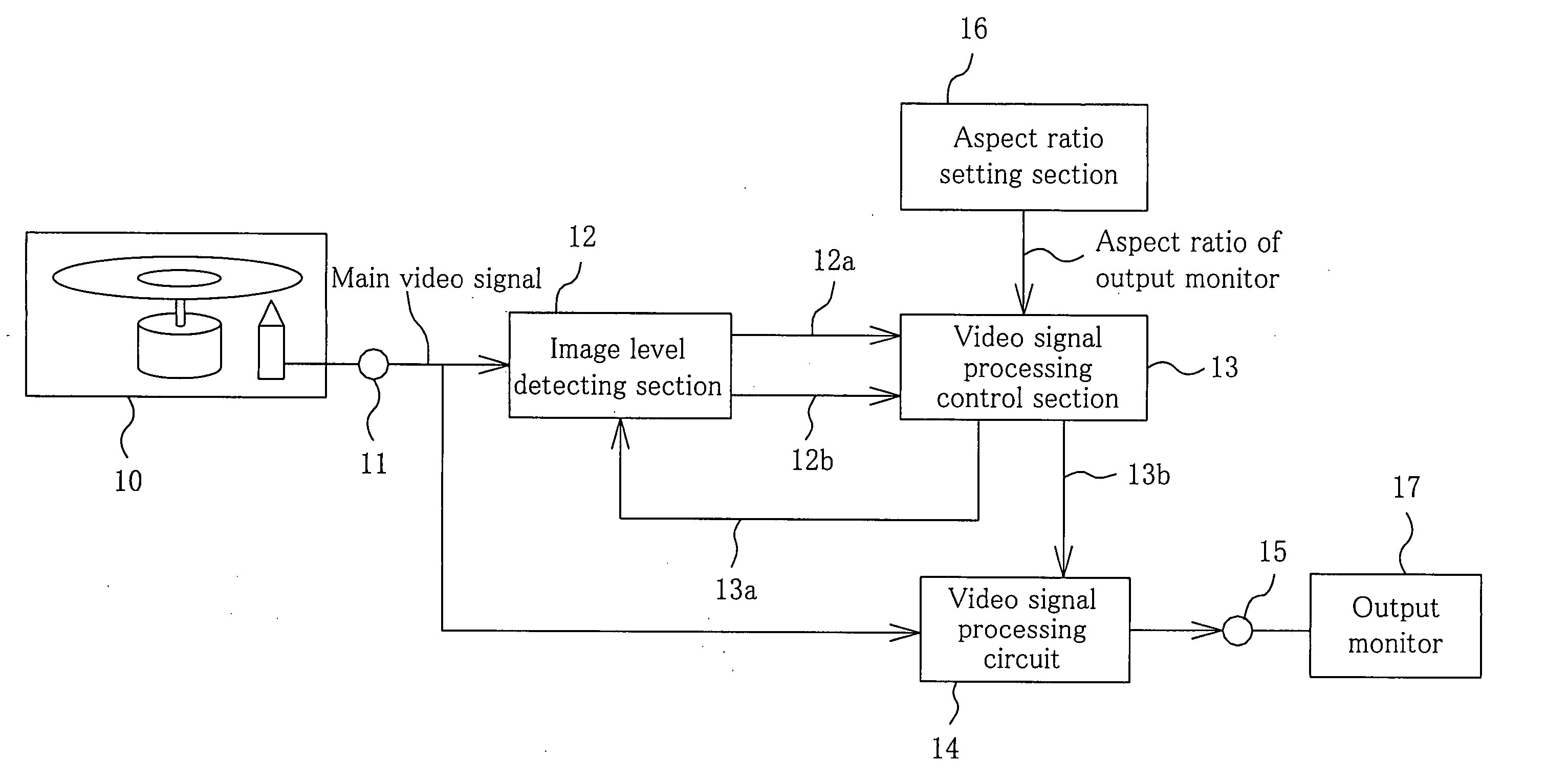
[0045]FIG. 1 is a block diagram illustrating the configuration of a video signal display unit according to a first embodiment of the present invention. As shown in FIG. 1, a video signal output section 10 reads an information signal recorded on a disc such as a DVD, transforms the information signal to an electrical signal, and outputs the electrical signal. The video signal output section 10 is connected through a video signal input terminal 11 to an image level detecting section 12 and a video signal processing circuit 14.

[0046] The image level detecting section 12 detects luminance signal levels in detection areas specified based upon a standard insert position where a non-picture area is inserted and upon a standard number of lines included in the non-picture area in one frame of an input video signal input from the video signal input terminal 11. The detection areas are changed one after another based on a first control signal 13a fed backed from a video signal processing cont...

second embodiment

[0068]FIG. 5 is a block diagram illustrating the configuration of a video signal display unit according to a second embodiment of the present invention. The video signal display unit of the second embodiment differs from that of the first embodiment only in that a sub video signal is superimposed on a main video signal in the second embodiment. The same members as those shown in the first embodiment are thus identified by the same reference numerals and different members will be only described.

[0069] As shown in FIG. 5, a video signal processing circuit 24 is connected to a sub video signal input terminal 27, so that a sub video signal such as subtitle information is input to the video signal processing circuit 24. A video signal processing control section 23 is connected to a sub video signal composition position setting section 28 for setting a composition position in which the sub video signal is superimposed on a main video signal.

[0070] The video signal processing control sec...

third embodiment

[0081]FIG. 8 is a block diagram illustrating the configuration of a video signal display unit according to a third embodiment of the present invention. The video signal display unit of the third embodiment differs from that of the first embodiment only in that a composite signal of a main video signal and a sub video signal is input from a video signal input terminal 11. The same members as those shown in the first embodiment are thus identified by the same reference numerals and different members will be only described.

[0082] As shown in FIG. 8, a composite video signal of a main video signal and a sub video signal is input to the video signal input terminal 11.

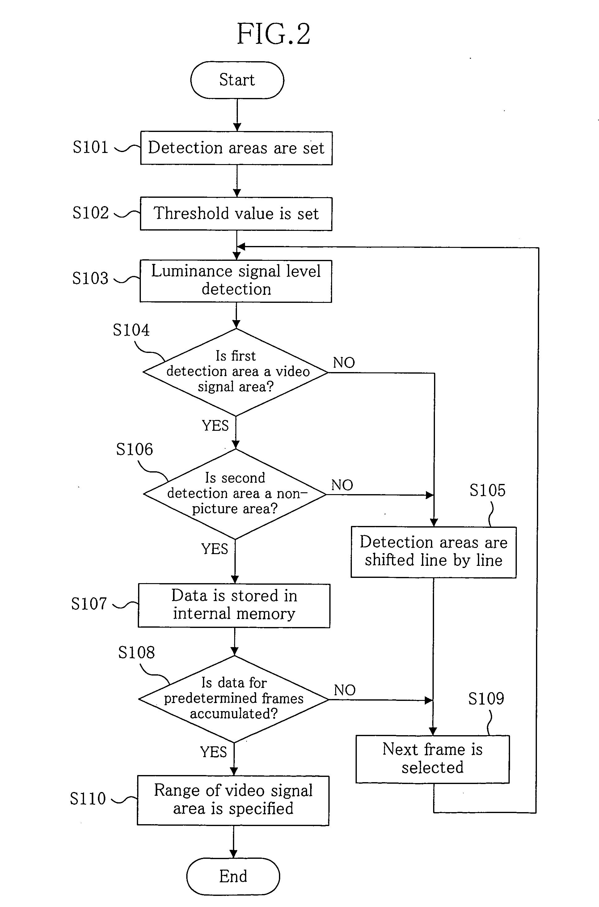
[0083] A video signal processing control section 33 analyzes features of the input video signal based on detection results obtained by an image level detecting section 12. The video signal processing control section 33 accumulates and analyzes data input for a predetermined number of frames, generates a first control signa...


PUM


Abstract

An image-level detecting section detects luminance levels in detection areas specified by a video signal processing control section. The video signal processing control section analyzes the detection results to determine the position and range of a non-picture area, and then calculates an optimum vertical magnification which allows only a video signal area to be displayed in the same size as the screen size of an output monitor. A video signal processing circuit clips only the video signal area based on a control signal provided from the video signal processing control section and magnifies the video signal area, thereby displaying the video signal area that should be viewed without causing any disappearance thereof.

Description

CROSS-REFERENCE TO RELATED APPLICATION [0001] The disclosure of Japanese Patent Application No.2004-006413 filed on Jan. 14, 2004 including specification, drawings and claims is incorporated herein by reference in its entirety. BACKGROUND OF THE INVENTION [0002] The present invention relates to video signal display units for changing broadcasted video signals, video signals (main video signals) recorded on disc media or the like, or sub video signals such as character information, to optimum image sizes according to output monitors. [0003]FIG. 10 illustrates an exemplary configuration of a conventional video signal display unit disclosed in Japanese Laid-Open Publication No. 2002-16884. The reference numeral 41 denotes a disc on which a video signal and a flag indicating the aspect ratio of the video signal are recorded. The reference numeral 42 represents a pickup for transforming the information signal recorded on the disc 41 to an electrical signal. The reference numeral 43 repre...

Claims


Application Information

Patent Timeline
Patent Type & Authority Applications(United States)
IPC IPC(8): H04N3/22H04N5/14H04N5/44H04N5/445H04N11/20
CPCH04N7/0122G06T3/40H04N21/4884
Inventor KIDA, EIKO
Owner PANASONIC CORP
Why Eureka
Try Eureka