Hydraulic machine

a technology of hydraulic machine and valve body, which is applied in the direction of rotary or oscillating piston engine, engine lubrication, rotary piston engine, etc., can solve the problems of short-circuiting between the high-pressure side and the low-pressure side, affecting the operation of the machine, and the damage of such a short-circuiting is extremely small, so as to achieve the effect of increasing the depth of the recess and being convenient to mak

Active Publication Date: 2005-08-18
WHITE DRIVE MOTORS & STEERING SP Z O O
View PDF10 Cites 13 Cited by
  • Summary
  • Abstract
  • Description
  • Claims
  • Application Information

AI Technical Summary

Benefits of technology

[0014] Preferably, the recess has a plane or concavely arched bottom. A recess of this kind is easily made, for example by milling. A plane bottom is made by a milling cutter. Depending on the diameter of the disc, a side-milling cutter can, under certain circumstances, produce a concavely arched bottom. As the remaining tooth side is arched, this will result in a gradually increasing depth of the recess. This is a simple way of achieving a variable throttle resistance, which reaches its highest value, when the pressure chamber in question has reached its maximum or its minimum volume.
[0015] Preferably, the recess is arranged in the axial centre of the toothing. Thus, possibly occurring asymmetric forces on the toothed set can be avoided. In the axial direction, the recess is relatively short. Accordingly, enough space for arranging the recess is available in the axial centre of the toothing.

Problems solved by technology

Of course, also the control of the valve arrangement has certain limits, which cannot be exceeded.
This will cause a short-circuiting between the high-pressure side and the low-pressure side.
As, however, this short-circuiting is only exposed to the highest pressure difference for a relatively short period, and as it is possible to have a certain influence on the amount of penetrating fluid by means of the size of the opening, the damaging effects of such a short-circuiting are extremely small.

Method used


Image

  • Hydraulic machine
  • Hydraulic machine
  • Hydraulic machine

Examples


Embodiment Construction

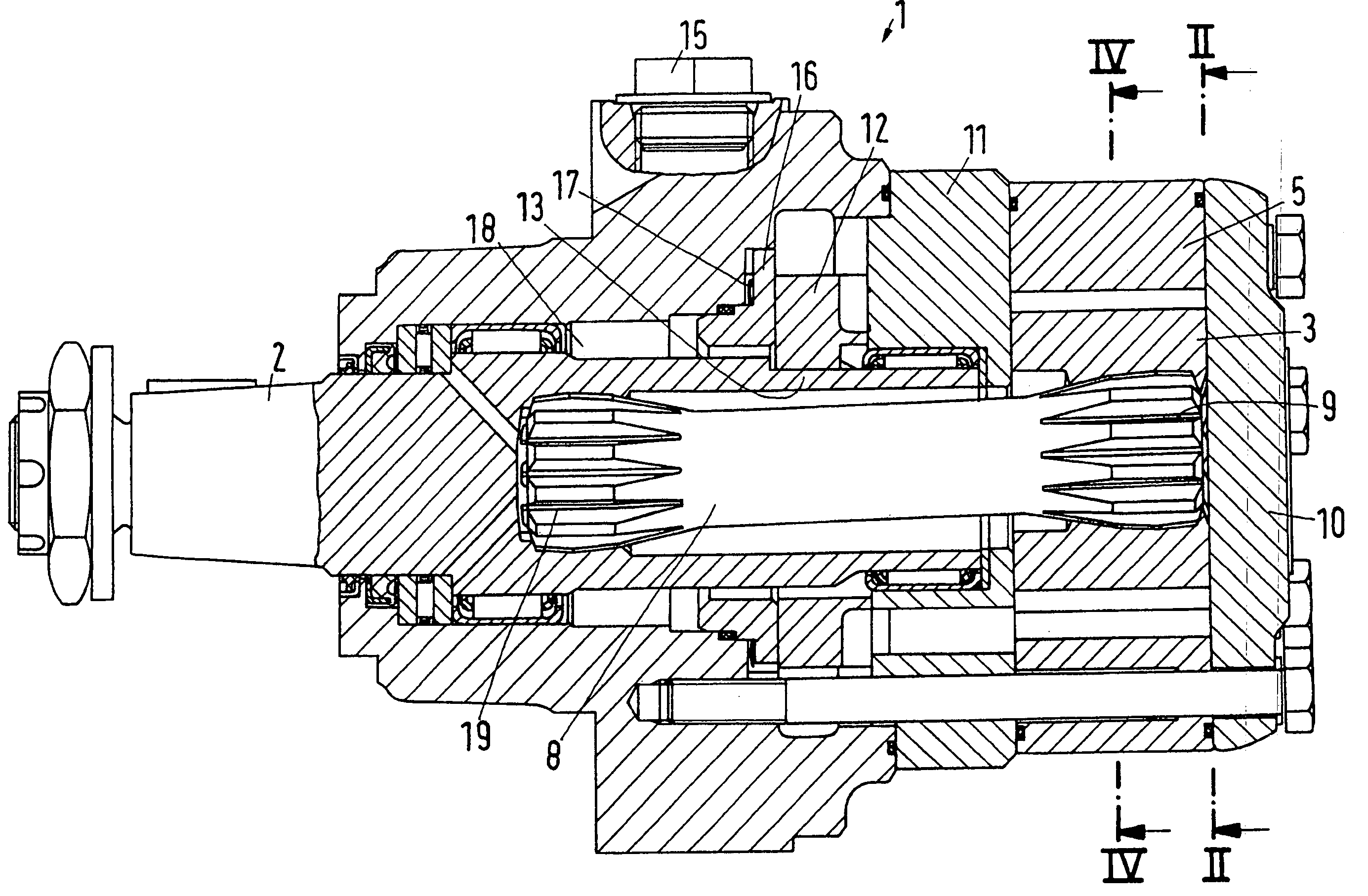
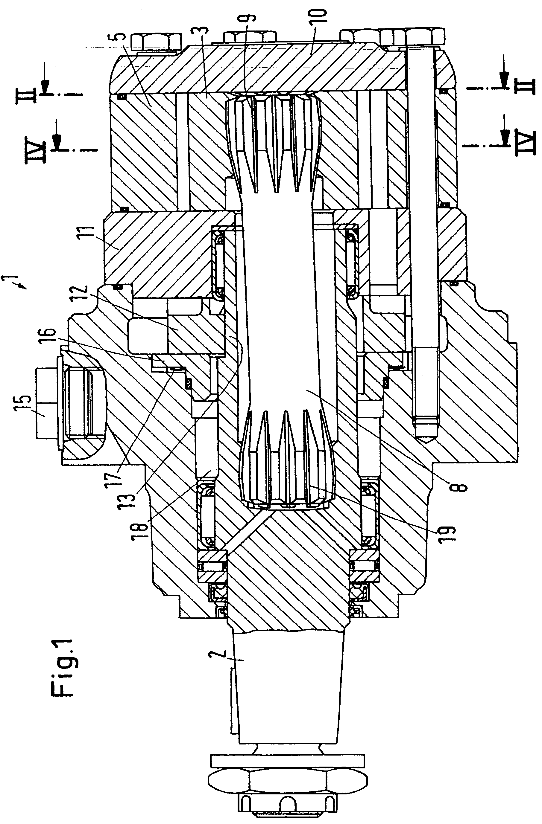
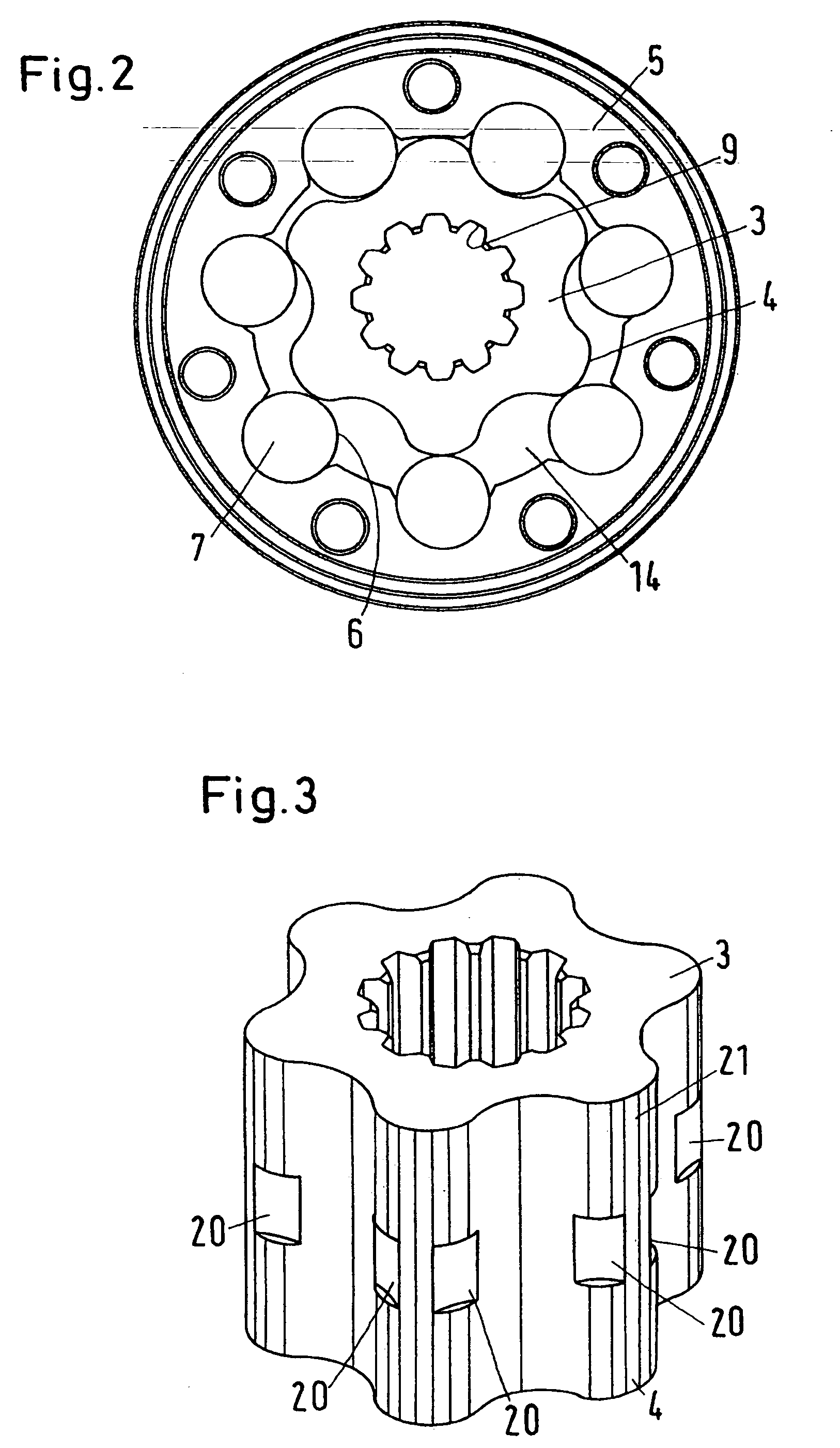
[0027] A machine shown in FIG. 1 is in the form of a motor 1, which has an output shaft 2. The output shaft 2 is driven by a gear wheel 3, which has an outer toothing 4 an rotates and orbits in a toothed ring 5, which has an inner toothing 6 in the shape of rollers 7. The output shaft 2 is connected with the gear wheel 3 via a cardan shaft 8, which is inserted into a suitable toothing 9 in the inside of the gear wheel 3.

[0028] On the side facing away from the cardan shaft 8, the toothed set consisting of the gear wheel 3 and the toothed ring 5 is covered by a cover plate 10. On the opposite side, the toothed set is covered by a channel plate 11, which cooperates with a valve plate 12. The valve plate 12 engages with an extension 13 of the output shaft 2, so that the valve plate 12 rotates synchronously with and at a predetermined angle relation to the gear wheel 3.

[0029] Together, the channel plate 11 and the valve plate 12 form a valve arrangement, which controls the supply from ...


PUM


Abstract

The invention concerns a hydraulic machine with a set of teeth, having a toothed ring with an inner toothing and a gear wheel with an outer toothing, the gear wheel rotating and orbiting in the toothed ring, the inner toothing and the outer toothing touching each other in contact areas, thus separating pressure chambers, and with a valve arrangement controlling a connection between a connection arrangement having a high pressure connection and a low pressure connection, and the pressure chambers. It is endeavoured to achieve a stable operation, particularly with low speeds. For this purpose, each contact area is provided with an opening, which, at the time when a pressure chamber reaches an extreme value of its volume, produces a short-circuiting with the neighbouring pressure chamber.

Description

CROSS-REFERENCE TO RELATED APPLICATIONS [0001] This application is entitled to the benefit of and incorporates by reference essential subject matter disclosed in International Application No. PCT / DK03 / 00124 filed on Feb. 27, 2003 and German Patent Application No. 10209672.4 filed on Mar. 5, 2002.FIELD OF THE INVENTION [0002] The present invention concerns a hydraulic machine with a set of teeth, having a toothed ring with an inner toothing and a gear wheel with an outer toothing, the gear wheel rotating and orbiting in the toothed ring, the inner toothing and the outer toothing touching each other in contact areas, thus separating pressure chambers, and with a valve arrangement controlling a connection between a connection arrangement having a high pressure connection and a low pressure connection, and the pressure chambers. BACKGROUND OF THE INVENTION [0003] A hydraulic machine of this kind is, for example, known from EP 0 959 248 A2. During motor operation, the valve arrangement s...

Claims


Application Information

Patent Timeline
Patent Type & Authority Applications(United States)
IPC IPC(8): F04C2/08F04C2/10
CPCF04C2/104F04C2/084
Inventor HANSEN, KIM RENEJOHANSEN, CLAUS JESPERANDERSEN, RENE SCHIBSBYE
Owner WHITE DRIVE MOTORS & STEERING SP Z O O
Why Eureka
Try Eureka