Test tube rack

a test tube and rack technology, applied in the field of test tube racks, can solve the problems of troublesome maintenance and increase in cost, and achieve the effect of preventing deformation of the test tube holding and improving durability

Inactive Publication Date: 2005-08-18
IDS CO LTD
View PDF4 Cites 40 Cited by
  • Summary
  • Abstract
  • Description
  • Claims
  • Application Information

AI Technical Summary

Benefits of technology

[0010] It is an object of the present invention to provide a test tube rack which prevents deformation of a test tube holding piece even if it is repeatedly used, and improves the durability.
[0013] According to this test tube rack, deformation of the test tube holding piece is prevented even if it is repeatedly used, and excellent durability is obtained.

Problems solved by technology

Thus, if more than one test tube adapter is arranged in the main body of the rack, the assembling workability is bad causing an increase in the cost.
Moreover, maintenance is troublesome if the O-ring is damaged.

Method used


Image

  • Test tube rack
  • Test tube rack
  • Test tube rack

Examples


first embodiment

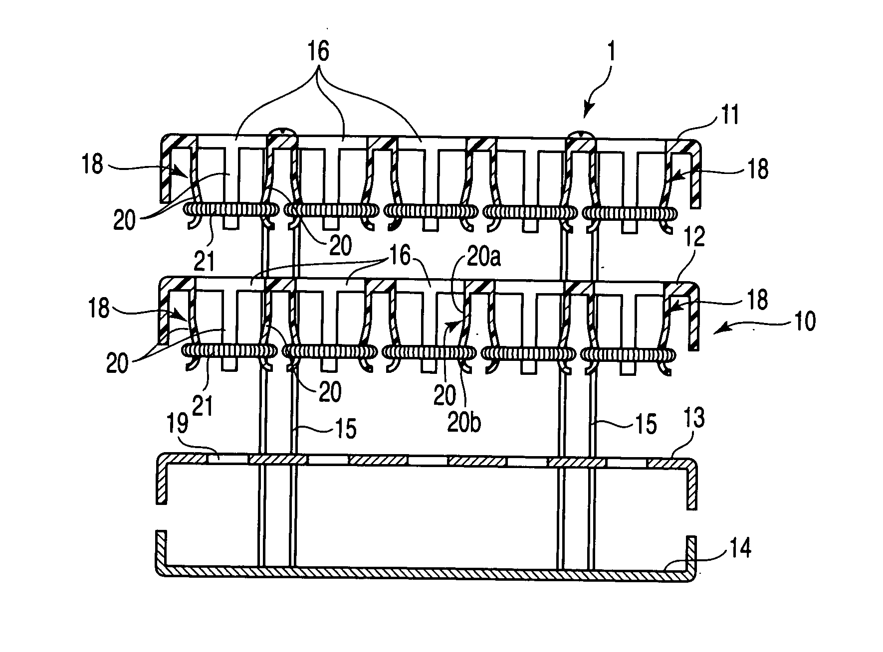
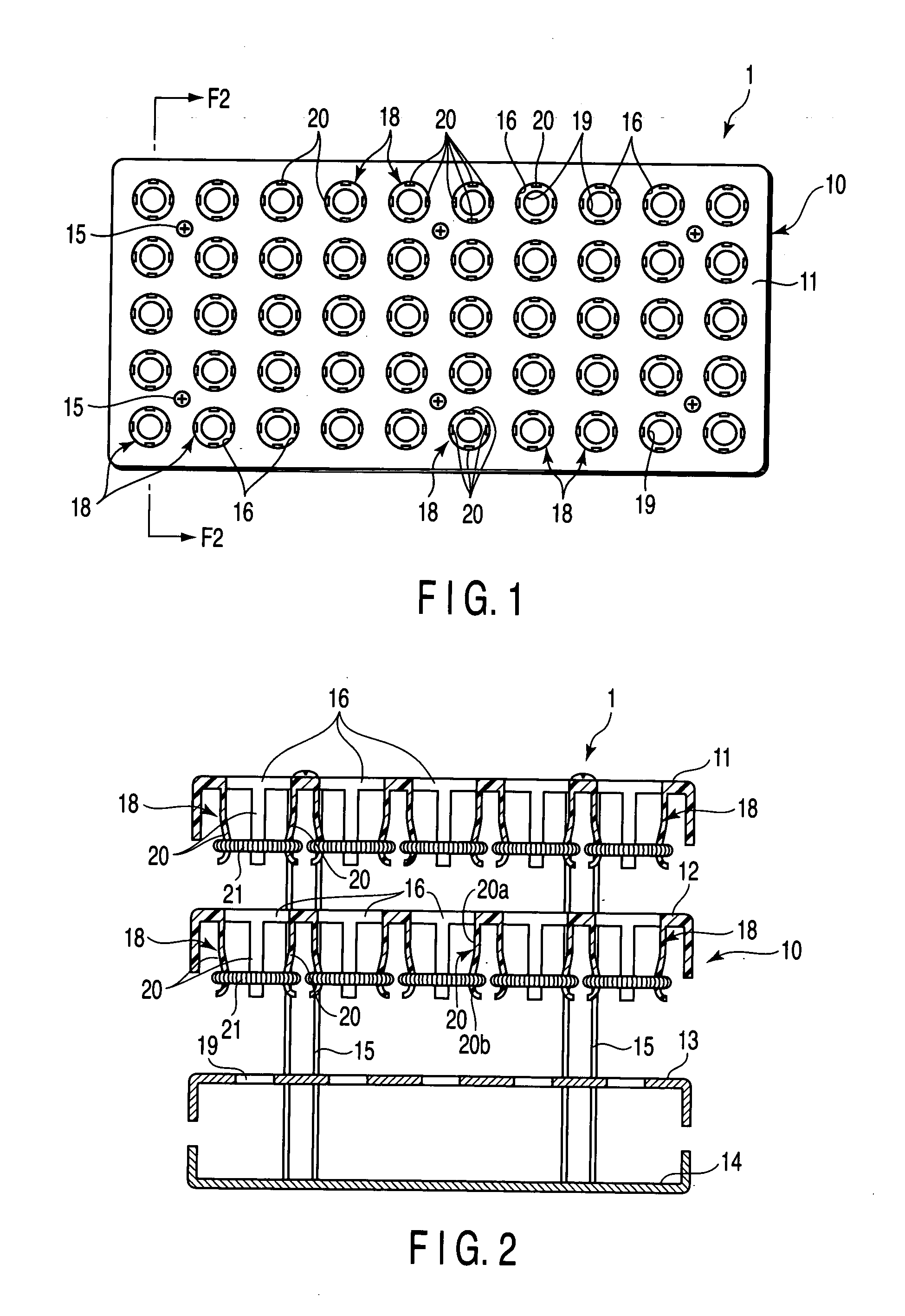
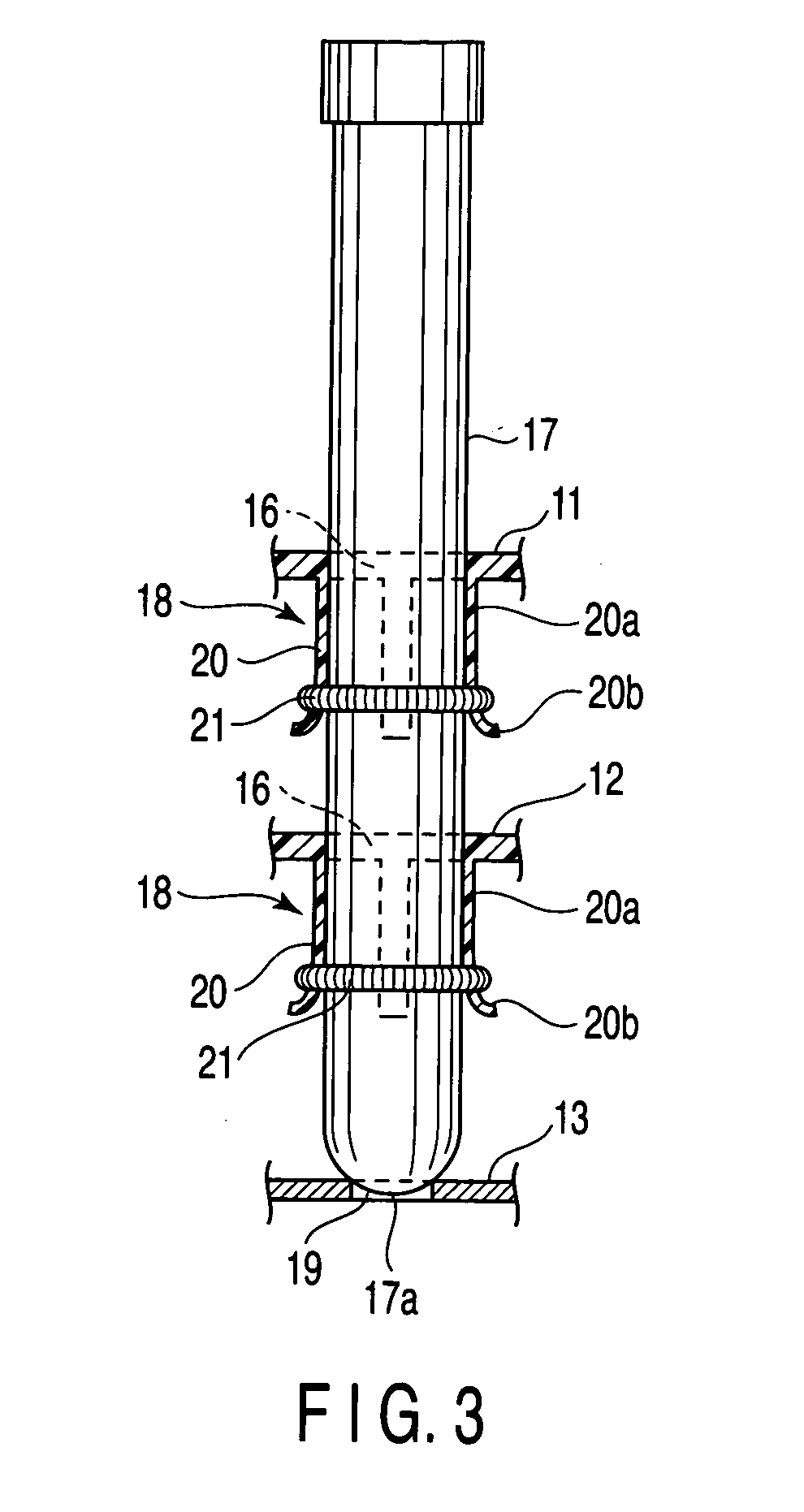
[0020] A first embodiment according to the present invention will be explained with reference to FIGS. 1 to 3. A test tube rack 1 shown in FIG. 1 has a rack main body 10, a test tube insertion hole 16, a test tube bottom receiving portion 19, and a test tube fitting adapter 18. The rack main body 10 is constructed in four stages in which an upper plate 11, a middle plate 12, a lower plate 13 and a base plate 14 are arranged parallel with an interval. The upper plate 11, middle plate 12, lower plate 13 and base plate 14 are connected and held parallel by a plurality of spacer bolts 15.

[0021] The upper plate 11 and middle plate 12 are made of synthetic resin and molded as one rectangular body. The lower plate 13 and base plate 14 are made of metal plate, for example, stainless steel, and formed rectangular with the same outside dimensions as those of the upper plate 11 and middle plate 12.

[0022] The upper plate 11 and middle plate 12 are formed with the same shape and dimensions. The...


PUM

PropertyMeasurementUnit
diameteraaaaaaaaaa
outer circumferenceaaaaaaaaaa
transparentaaaaaaaaaa

Abstract

A test tube rack has a rack main body, a test tube insertion hole, a test tube bottom receiving part, and a test tube fitting adapter. The rack main body is constructed in at least three stages in which an upper plate, a middle plate and a lower plate are arranged parallel with an interval. The test tube insertion hole is provided on the upper plate and middle plate. The test tube bottom receiving part is provided in the lower plate. The test tube fitting adapter is provided in the test tube insertion hole, and supports a test tube with a different outside diameter. The test tube is supported at three positions such as the upper plate,the middle plate, and the lower plate, and held in the vertically stood state.

Description

CROSS-REFERENCE TO RELATED APPLICATIONS [0001] This application is based upon and claims the benefit of priority from prior Japanese Patent. Application No. 2004-040023, filed Feb. 17, 2004, the entire contents of which are incorporated herein by reference. BACKGROUND OF THE INVENTION [0002] 1. Field of the Invention [0003] The present invention relates to a test tube rack which is used to store a test tube containing a sample such as blood, and to carry the test tube for serving or pouring the sample to a test tube. [0004] 2. Description of the Related Art [0005] A test tube containing a sample such as blood is made of transparent glass, and the upper end opening is stopped by a cap made of rubber or synthetic resin. A test tube is stored and carried along a carrying path in the state held vertically in a test tube rack, in order to store the test tube with the sample contained or to carry the test tube to respective processing sections to serve or pour the sample to a test tube. [...

Claims


Application Information

Patent Timeline
Patent Type & Authority Applications(United States)
IPC IPC(8): B01L9/00G01N1/00B01L9/06G01N35/04
CPCB01L2200/025B01L9/06E02D29/124E02D29/125E02D29/127E03F5/02B01L2300/0809
Inventor ITOH, TERUAKI
Owner IDS CO LTD
Why Eureka
Try Eureka