Method for designing redox flow battery system

a technology of redox flow and battery system, which is applied in the direction of indirect fuel cells, non-aqueous electrolyte cells, cell components, etc., can solve the problems of not knowing the optimal method of designing a redox flow battery, the improvement of the loss caused, and the inability to take an improvement, so as to achieve the effect of improving system efficiency and reducing system loss

a technology of redox flow and battery system, which is applied in the direction of indirect fuel cells, non-aqueous electrolyte cells, cell components, etc., can solve the problems of not knowing the optimal method of designing a redox flow battery, the improvement of the loss caused, and the inability to take an improvement, so as to achieve the effect of improving system efficiency and reducing system loss

US20050181273A1Inactive Publication Date: 2005-08-18SUMITOMO ELECTRIC IND LTD +1

Image

  • Method for designing redox flow battery system
  • Method for designing redox flow battery system
  • Method for designing redox flow battery system

Examples


example

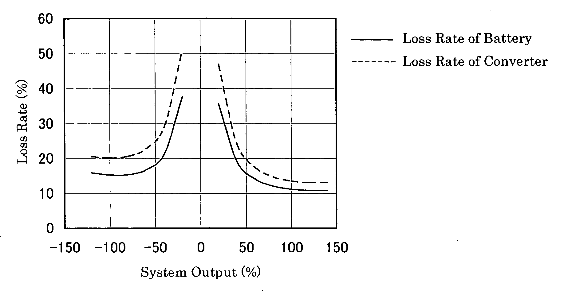
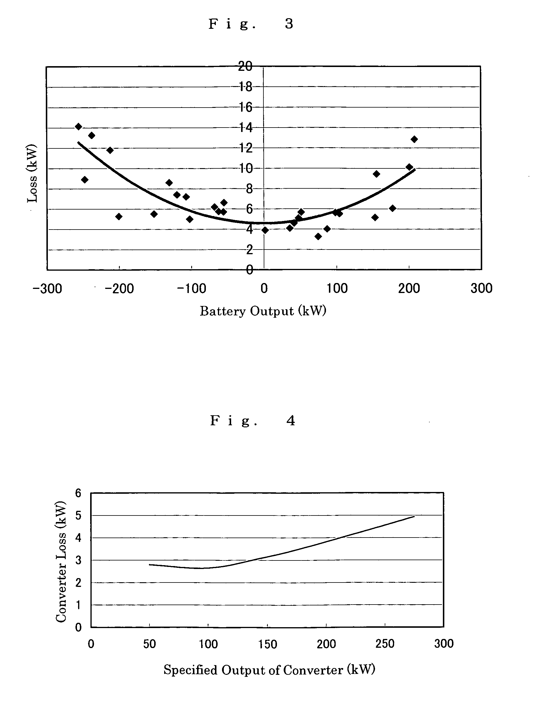
[0091] A redox flow battery system including generating equipment that varies irregularly in output of power generation, a redox flow battery for smoothing the irregular output of power generation, and a DC / AC converter for converting the battery output was produced, and the loss characteristic of the battery and that of the converter were examined.

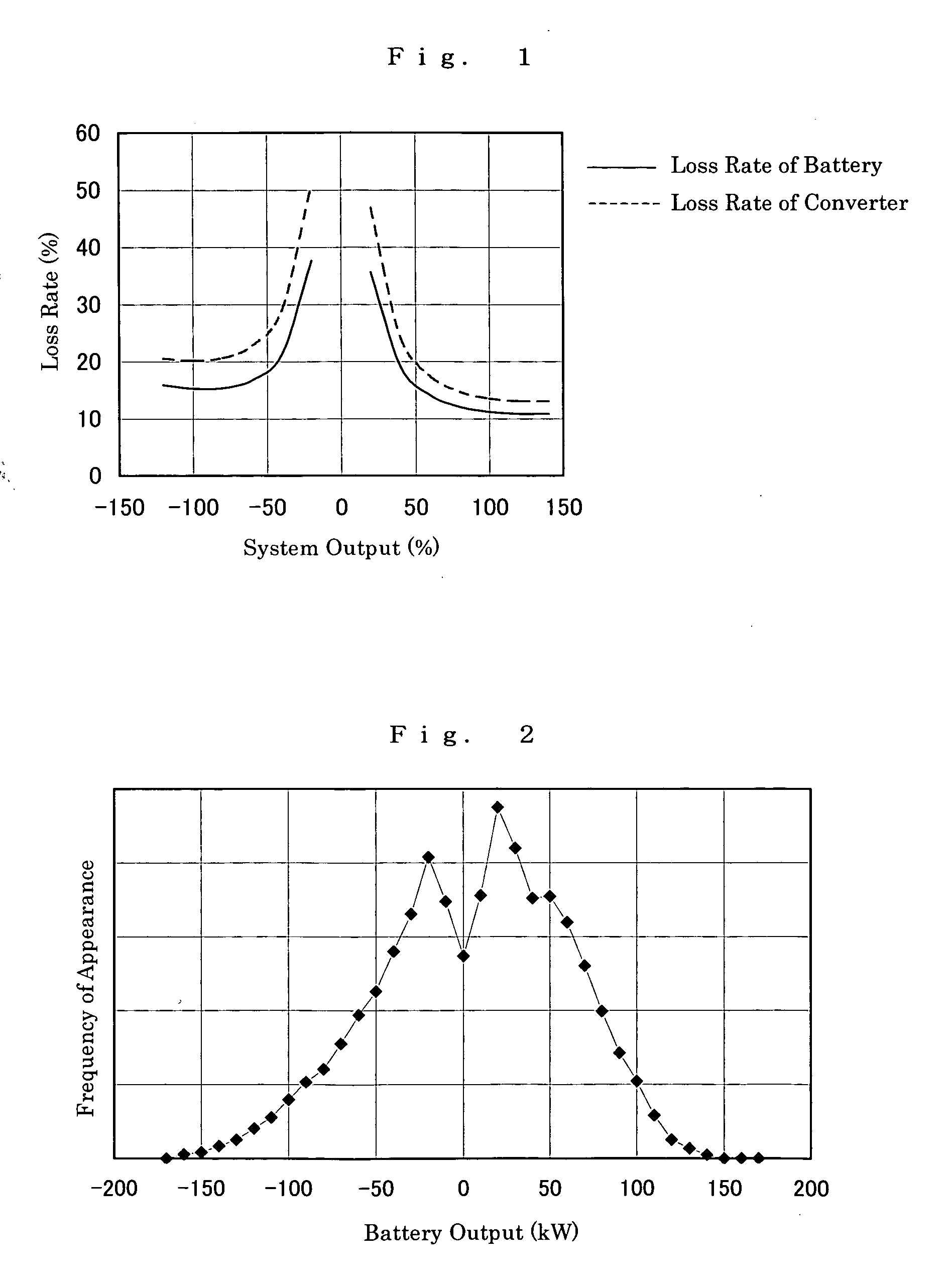
[0092] A power generation by wind having a maximum output of power generation of 400 kW (specified output of power generation: 275 kW) was used as the generating equipment. A redox flow battery having the construction shown in FIG. 8 was produced as the redox flow battery and set at a specified battery output of 170 kW (about 60% of the specified output of power generation). A DC / AC converter having a specified converter output of 275 kW was used. A histogram of 8-hour battery output for the battery system comprising the generating equipment, the redox flow battery and the converter is shown in FIG. 2. The distribution characteristic is ...


PUM


Abstract

The present invention provides a method of designing a redox flow battery system that can prevent system efficiency loss caused by weak generation power or load power at the time of electric charge or discharge, without using any lead storage battery, and can also provide further improved system efficiency. In the present invention, generating equipment that varies irregularly in output of power generation is provided with the redox flow battery to smooth the output of power generation. An average value of output distribution of the battery with respect to the smoothed output of power generation and standard deviation are determined. Then, at least either of a specified output of the battery and a specified output of the converter for converting the battery output is determined based on the standard deviation.

Description

TECHNICAL FIELD [0001] The present invention relates to a method of designing a redox flow battery system including a redox flow battery to force electrolytic solution to be fed to and discharged from its cells. Particularly, the present invention relates to a method of designing a redox flow battery system that can reduce a battery system loss. BACKGROUND ART [0002] It is inherent in the electric power supply that power supply conforming to electricity consumption, what is called “simultaneous supply of equivalent electricity” is required. Meanwhile, developments of new energy resources, including power generation by wind and solar photovoltaic power generation, have been made increasingly in recent years. However, the power generation by wind, the solar photovoltaic power generation, and the like are all power sources which are irregular in output of power generation, due to which these power sources cannot serve as a satisfactory power supply source by themselves. Consideration i...

Claims


Application Information

Patent Timeline
18 Aug 2005
Publication
US20050181273A1
IPC
H01M8/04; H01M8/18; H01M8/20
CPC
H01M8/0432; H01M8/04328; H01M8/04335; Y02E60/528; H01M8/04395; H01M8/04626; H01M8/188; H01M8/04388
Inventors
DEGUCHI, HIROSHIGE; SHIGAMATSU, TOSHIO