
Automatic threshold selection method for improving the detection of a wireless signal

a wireless signal and automatic threshold selection technology, applied in the field of digital communications, can solve the problems of increasing power consumption, reducing battery life, and high probability of communication devices erroneously decoding indicator channels, and achieve the effect of improving the detection performance of wireless transmitted signals

Active Publication Date: 2005-08-18
TEXAS INSTR INC
View PDF6 Cites 64 Cited by
  • Summary
  • Abstract
  • Description
  • Claims
  • Application Information

AI Technical Summary

Benefits of technology

[0010] These and other problems are generally solved or circumvented, and technical advantages are generally achieved, by preferred embodiments of the present invention which provides for a system and method for improving the detection performance of a wireless transmitted signal.
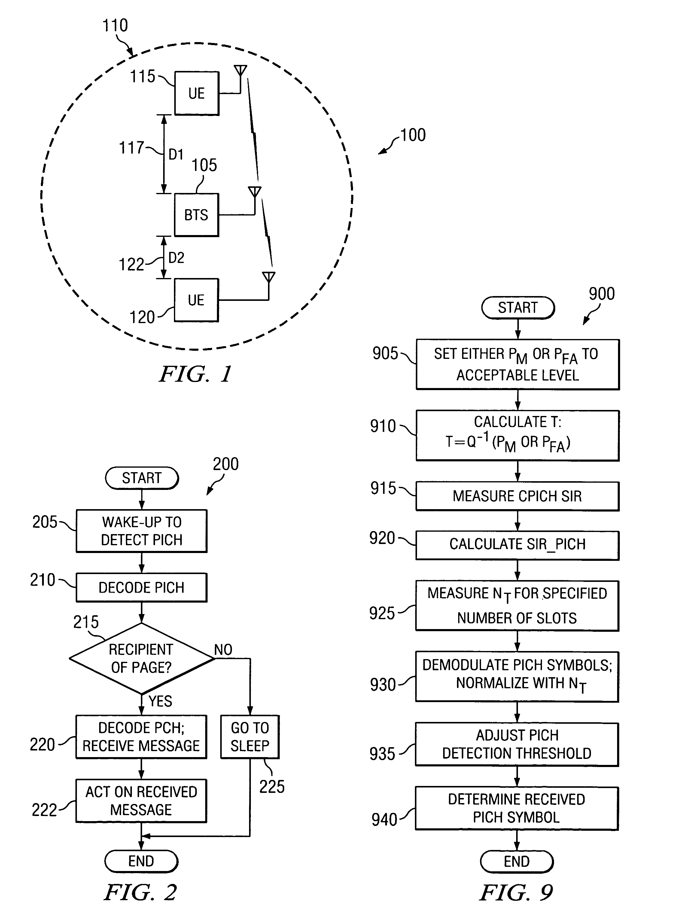
[0013] An advantage of a preferred embodiment of the present invention is that it is possible to design a customized response for either the missed detection or false alarm probability across the range of SNRs (or equivalently, across different locations in the coverage area of a communications cell). A customized response may be desirable since the indicator channel detection performance can be one component of overall missed call performance and the sensitivity of the overall paging channel detection performance to the indicator channel detection may not be uniform across the range of SNRs.
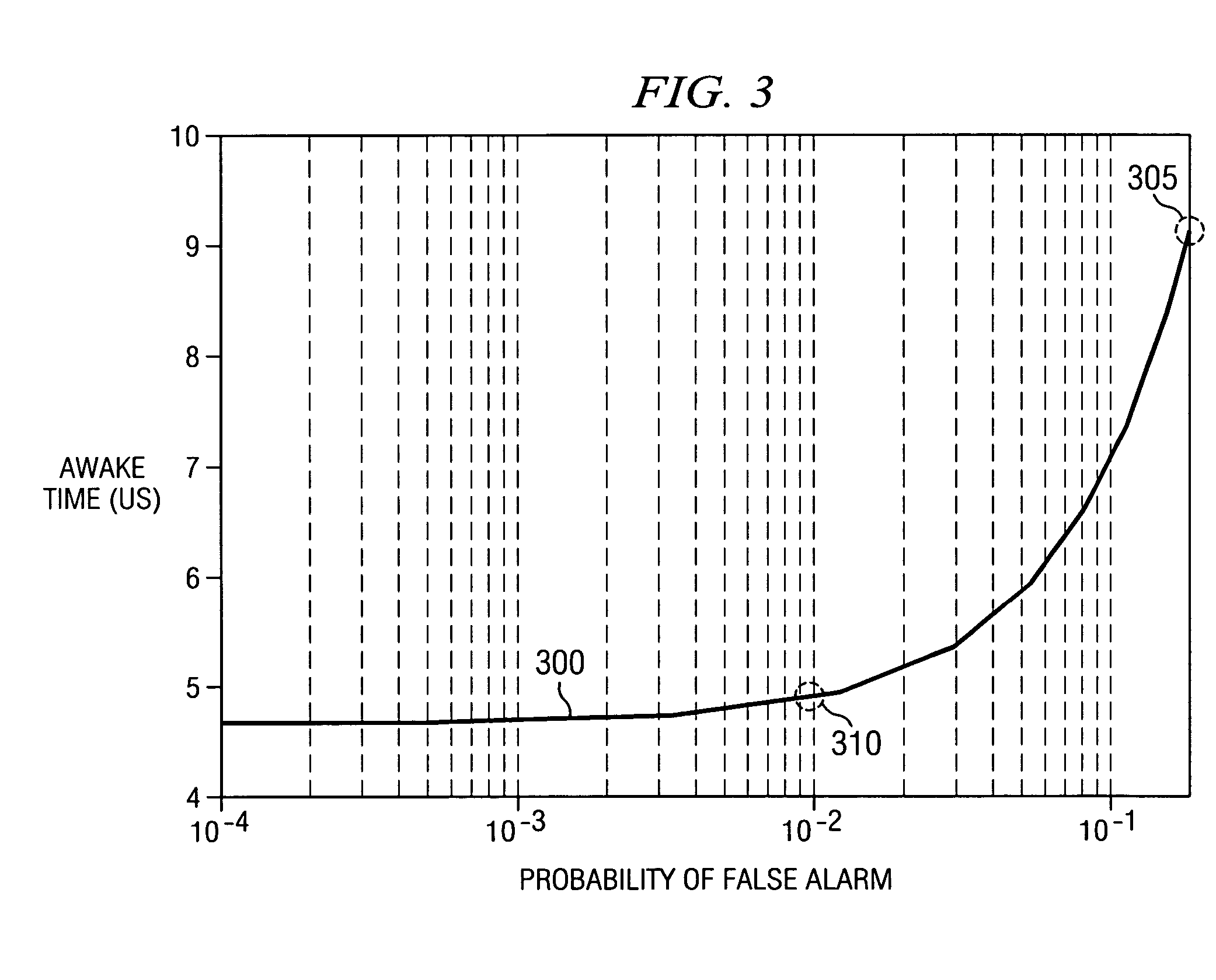
[0014] A further advantage of a preferred embodiment of the present invention is that it can permit the capping of the false alarm probability to a value where its influence on the overall power consumption (and battery life) of the communications device is negligible. With the false alarm probability capped, it can be possible to reduce the missed indicator channel detection probability. This can allow for the customization of the missed indicator channel detection probability in certain SNR ranges and the false alarm probability in other SNR ranges.
[0015] Yet another advantage of a preferred embodiment of the present invention is that it is possible to correctly calculate the noise variance that is to be used in threshold setting. The noise variance calculation in the present invention can correctly account for noisy channel estimates used in PICH demodulation. This accurate calculation of the noise variance can also help in the detection based upon the NP method.

Problems solved by technology

When the SNR of the indicator channel is low, then the probability of the communications device erroneously decoding the indicator channel can be high.
If the indicator channel is erroneously decoded, the communications device may erroneously decode the indicator channel one of two ways: a false alarm or a missed page.
With a false alarm, the communications device would decode the indicator channel as indicating that there is an incoming page when there isn't one, thereby unnecessarily increasing power consumption and reducing battery life.
While with the missed page, the communications device would decode the indicator channel as not indicating that there is an incoming page when there is an incoming page resulting in a missed call (since the presence of a page is usually followed by a call).
One disadvantage of the prior art is that the ML method permits only the assignment of equal costs for erroneously decoding the state of the indicator channel as either a missed page or false alarm.
These assumptions are incorrect in real-world applications and their use can result in poor performance.
A second disadvantage of the prior art is that the NP approach does not adapt the threshold by taking into consideration the fact that the sensitivity of the overall performance metrics (battery life and missed call rate) to PICH detection may change over an entire range of SNRs (or equivalently, the location of the communications device in relation to a cell site).

Method used


Image

  • Automatic threshold selection method for improving the detection of a wireless signal
  • Automatic threshold selection method for improving the detection of a wireless signal
  • Automatic threshold selection method for improving the detection of a wireless signal

Examples


Embodiment Construction

[0027] The making and using of the presently preferred embodiments are discussed in detail below. It should be appreciated, however, that the present invention provides many applicable inventive concepts that can be embodied in a wide variety of specific contexts. The specific embodiments discussed are merely illustrative of specific ways to make and use the invention, and do not limit the scope of the invention.

[0028] The present invention will be described with respect to preferred embodiments in a specific context, namely a UMTS wireless communications system using a paging indicator channel. An introduction to the technical specifications for a UMTS wireless communications system may be found in a document entitled “3rd Generation Partnership Project; Technical Specifications Group Services and System Aspects General UMTS Architecture (Release 4),” published March 2004. The invention may also be applied, however, to other wireless communications systems that make use of an indi...


PUM


Abstract

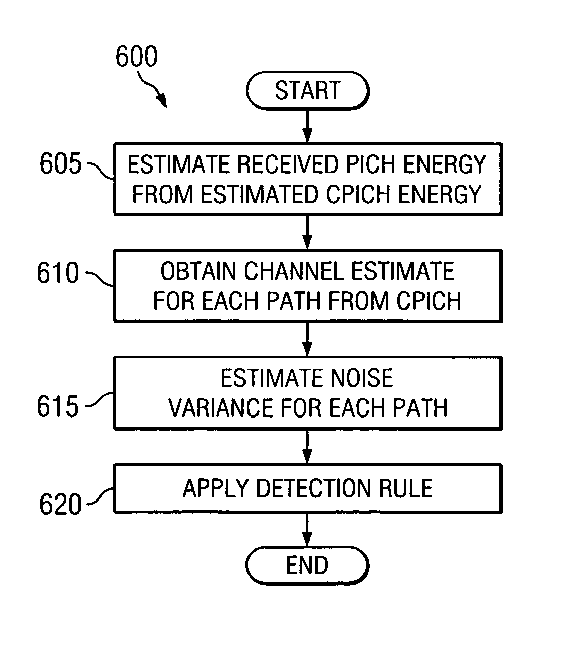
System and method for improving the detection performance of a wirelessly transmitted signal. A preferred embodiment comprises specifying a desired response for missed channel detection and false alarm probabilities for a plurality of signal qualities and determining if a channel detection threshold is based on missed channel detection or false alarm probabilities for the plurality of signal qualities. A signal quality estimate of a channel can be inferred from a signal quality measurement of a second channel, wherein the channel and the second channel are sourced by a single transmitter. The channel detection threshold can be adjusted based upon the previously determined required response and the signal quality estimate of the channel.

Description

[0001] This application claims the benefit of U.S. Provisional Application No. 60 / 545,420, filed Feb. 17, 2004, entitled “Automatic Threshold Selection Method for Improving the Detection of a Wireless Signal” which application is hereby incorporated herein by reference.TECHNICAL FIELD [0002] The present invention relates generally to a method for digital communications, and more particularly to a method for improving the detection performance of a wirelessly transmitted signal. BACKGROUND [0003] In many wireless communications systems, such as Universal Mobile Telephony Systems (UMTS) and other third generation (3GPP) wireless communications systems, a communications device is often put into a sleep mode in order to decrease power consumption and increase battery life. The communications device can then wake up at fixed intervals to check if it is the recipient of an incoming page. In UMTS, this is referred to as the DRX mode, or discontinuous reception mode. [0004] To further reduc...

Claims


Application Information

Patent Timeline
IPC IPC(8): H04B7/14
CPCH04W52/0216H04B1/1027Y02D30/70
Inventor ASGHAR, ZIADJEONG, GIBONGSAMPATH, ASHWIN
Owner TEXAS INSTR INC
Learn More