
Connecting structure for a striking plate of a golf club head

Inactive Publication Date: 2005-08-18
FUSHENG IND CO LTD
View PDF9 Cites 8 Cited by
  • Summary
  • Abstract
  • Description
  • Claims
  • Application Information

AI Technical Summary

Benefits of technology

[0007] An object of the present invention is to provide a connecting structure for connecting a striking plate to a body of a golf club head, thereby positioning the striking plate and simplifying assembling and positioning for a subsequent welding procedure. The bonding strength is improved, and the manufacturing cost is reduced.
[0008] Another object of the present invention is to provide a golf club head with improved welding strength.
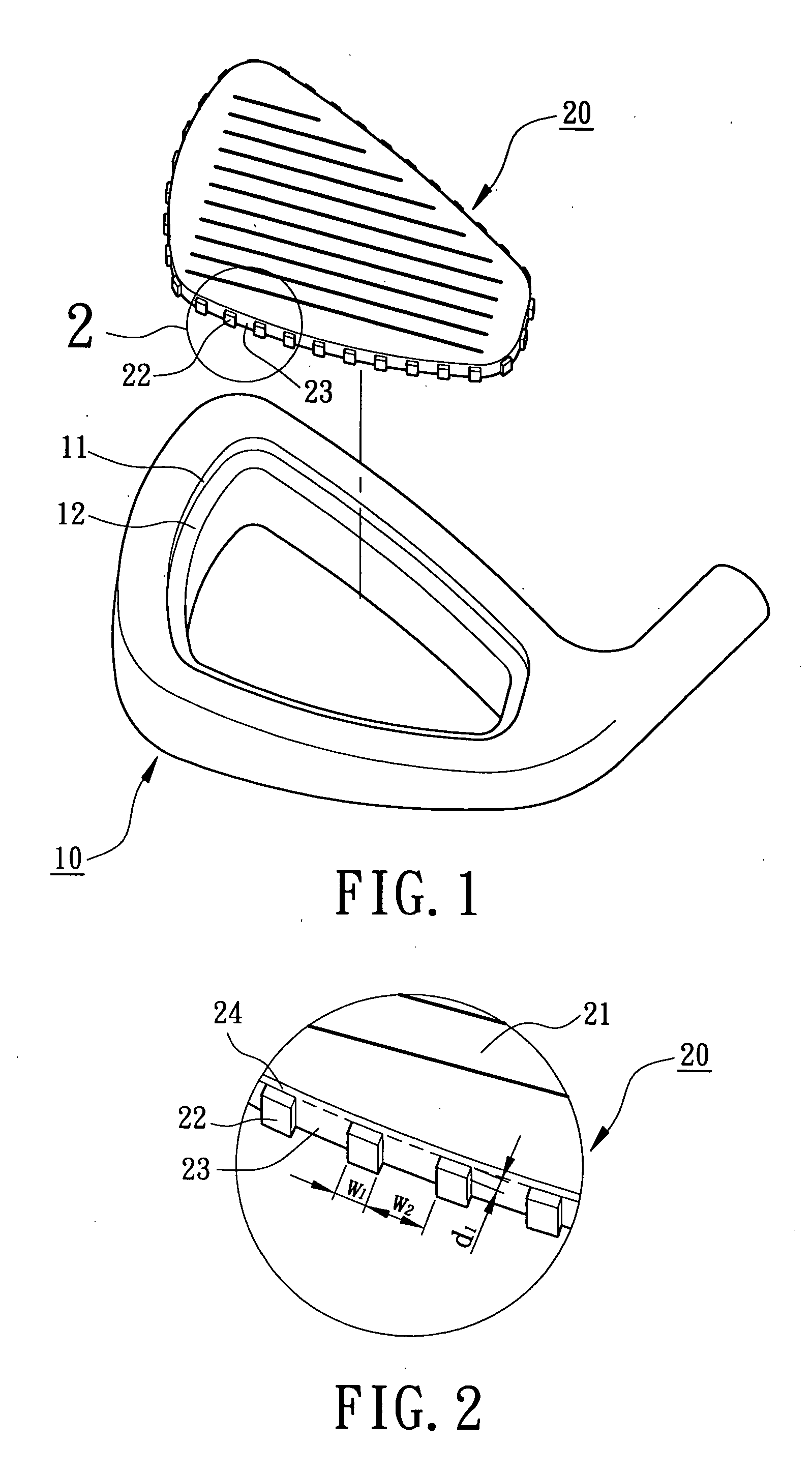
[0010] In accordance with an aspect of the present invention, a golf club head comprises a body and a striking plate. The body includes a recess in a front side thereof. The striking plate includes a striking face on a front side thereof for striking a golf ball. A plurality of positioning protrusions project from a perimeter of the striking plate. When the striking plate is inserted into the recess of the body, the positioning protrusions plastically deform and engage with an inner perimeter delimiting the recess, thereby positioning the striking plate in the recess and simplifying assembling and positioning for a subsequent welding procedure.
[0011] In accordance with another aspect of the present invention, a golf club head comprises a body and a striking plate. The body includes a recess in a front side thereof. A plurality of positioning protrusions project from an inner perimeter delimiting the recess. The striking plate includes a striking face on a front side thereof for striking a golf ball. When the striking plate is inserted into the recess of the body, the positioning protrusions plastically deform and engage with a perimeter of the striking plate, thereby positioning the striking plate in the recess and simplifying assembling and positioning for a subsequent welding procedure.

Problems solved by technology

Nevertheless, the gap between the striking plate, the shoulder, and the protruded portion can receive a limited amount of welding material, with a portion of the welding material filling the tiny gaps between an inner perimeter delimiting the recess and an outer perimeter of the striking plate.
Thus, the remaining welding material is insufficient to fill the gap between the striking plate, the shoulder, and the protruded portion.
As a result, when the striking plate is subjected to a striking stress and thus elastically deforms, cracks are apt to be generated in the welding areas.
The overall time for manufacturing the golf club head and the manufacturing cost are both increased, which is detrimental to mass production.
Nevertheless, the tolerance between the golf club head body and the striking plate requires precise control.
Further, the overall time for manufacturing the golf club head and the manufacturing cost are both increased, which is detrimental to mass production.

Method used


Image

  • Connecting structure for a striking plate of a golf club head
  • Connecting structure for a striking plate of a golf club head
  • Connecting structure for a striking plate of a golf club head

Examples


first embodiment

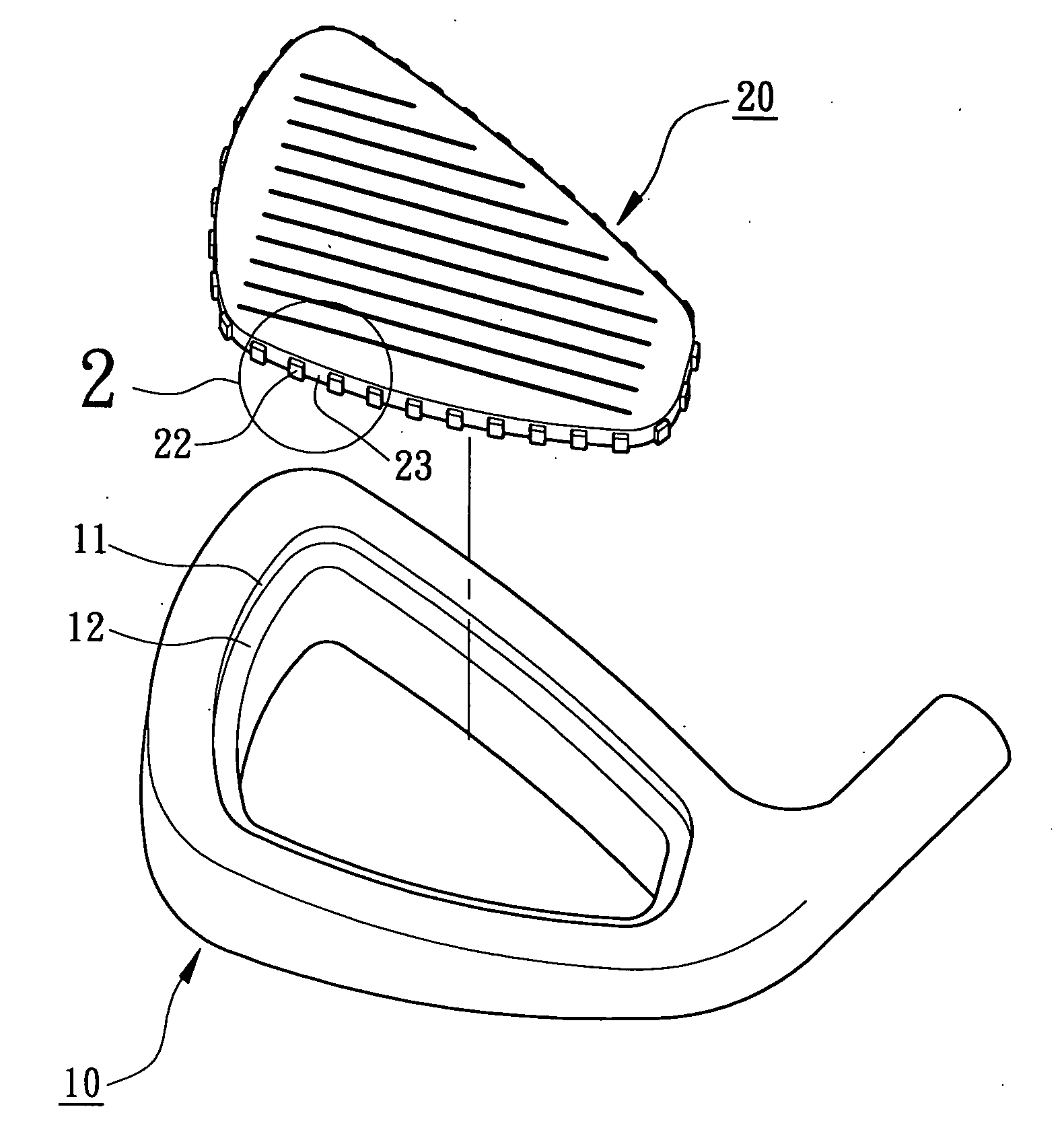
[0026] Referring to FIGS. 1 and 2, a golf club head in accordance with the present invention comprises a body 10 and a striking plate 20. The body 10 is made of stainless steel, carbon steel, or titanium alloy and has a recess 11. The recess 11 of the body 10 includes a stepped portion 12 extending inward from an inner perimeter delimiting the recess 11. The rear side of the recess 11 may be open or sealed.

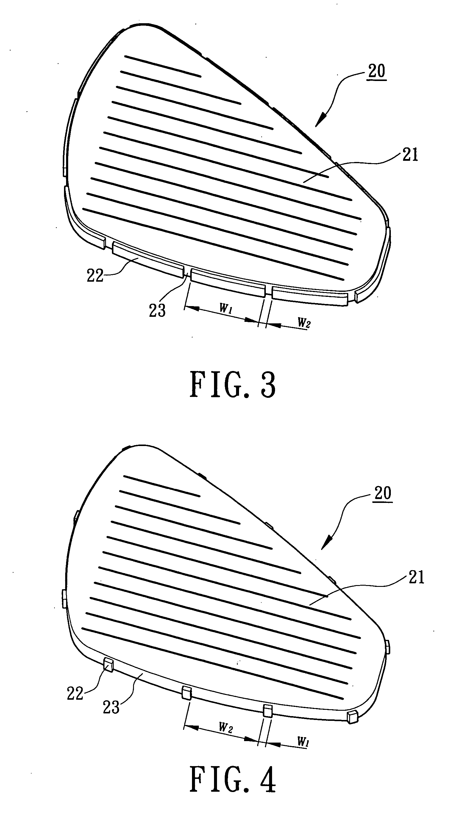
[0027] The striking plate 20 is made of titanium, titanium alloy, or stainless steel that has a good elastic deformability. The striking plate 20 includes a striking face 21 on a front side thereof for striking a golf ball. Further, a plurality of positioning protrusions 22 project from a perimeter of the striking plate 20, with a buffering space 23 being defined between two positioning protrusions 22 adjacent to each other. In this embodiment, each positioning protrusion 22 is a parallelepiped extending from a bottom edge of the perimeter of the striking plate 20 toward a top edg...

second embodiment

[0034] Referring to FIGS. 12 and 13, the golf club head in accordance with the present invention comprises a body 10 and a striking plate 20. The body 10 includes a recess 11 having a stepped portion 12. In this embodiment, a plurality of positioning protrusions 13 project from an inner perimeter delimiting of the recess 11 of the body 10, with a buffering space 14 being defined between two positioning protrusions 13 adjacent to each other. Each positioning protrusion 13 may be a parallelepiped, trapezoid column, semi-cylinder, or a triangular prism illustrated in the above embodiments. In this embodiment, each positioning protrusion 13 is a parallelepiped extending from a bottom edge of the inner perimeter delimiting the recess 11 toward a top edge of the inner perimeter delimiting the recess 11. As illustrated in FIG. 13, preferably, a space 15 for receiving filler is defined between each positioning protrusion 13 and a top edge of the inner perimeter delimiting the recess 11.

[003...


PUM


Abstract

A golf club head includes a body and a striking plate. The body includes a recess in a front side thereof. A plurality of positioning protrusions project from a perimeter of the striking plate. When the striking plate is inserted into the recess of the body, the positioning protrusions plastically deform and engage with an inner perimeter delimiting the recess, thereby positioning the striking plate in the recess and simplifying assembling and positioning for a subsequent welding procedure. In another embodiment, the positioning protrusions project from the inner perimeter delimiting the recess, and when the striking plate is inserted into the recess of the body, the positioning protrusions plastically deform and engage with the perimeter of the striking plate.

Description

BACKGROUND OF THE INVENTION [0001] 1. Field of the Invention [0002] The present invention relates to a connecting structure for a striking plate of a golf club head. In particular, the present invention relates to a connecting structure for connecting a striking plate to a body of a golf club head for simplifying assembling and positioning for a subsequent welding procedure. [0003] 2. Description of Related Art [0004] Taiwan Patent Publication No. 327606 discloses a method for connecting a golf club head body and a striking plate, both made of metal. The golf club head body includes a recess for engaging with the striking plate. The recess includes a shoulder on which a welding material is placed. The striking plate is inserted into the recess and presses against the shoulder to cause deformation of a protruded portion on an inner edge of the shoulder, thereby filling the welding material into a gap defined between the striking plate, the shoulder, and the protruded portion. The wel...

Claims


Application Information

Patent Timeline
IPC IPC(8): A63B53/04
CPCA63B53/04A63B53/047A63B2053/0416A63B53/0416A63B60/00
Inventor HUANG, CHUN-YUNG
Owner FUSHENG IND CO LTD
Learn More