Reciprocating table saw

a table saw and reciprocating technology, applied in the field of power tools, can solve the problems of slow hand saws, unsuitable for construction site use, laborious and labor-intensive circular saws, and inability to make long, accurate cuts in large panels, and achieve the effect of limiting sideways displacemen

Inactive Publication Date: 2005-08-25
RUE JERRY RANDALL
View PDF18 Cites 34 Cited by
  • Summary
  • Abstract
  • Description
  • Claims
  • Application Information

AI Technical Summary

Benefits of technology

[0010] In yet another aspect there is disclosed a blade guide supported by the work table and disposed away from the first side of the work table adjacent the axis of reciprocation and embracing the second end of the saw blade to limit sideways displacement of the second end of the saw blade relative to the axis of reciprocation while cutting the workpiece. The blade guide may be supported by a cantilevered support arm extending from a side of the work table. Alternatively, the blade guide may be supported by a non-cutting blade member disposed rearward of the cutting blade and in the same plane as the cutting blade such that the non-cutting blade occupies the kerf formed by the cutting blade. In yet another aspect the non-cutting blade member may be used as a damping strap to damp vibratory motion of the cantilevered support arm.

Problems solved by technology

However, hand saws are slow, labor intensive and not well-suited to construction site uses.
While powered saws are faster, circular saws do not have the ability to cut to a precise depth completely through a panel and reciprocating saws, while useful for making small cuts or blind cuts, are not suited for making long, accurate cuts in large panels.
A powered hacksaw is well adapted to cutting metal bar stock but not large panels without building a custom-made unit, which would be cost-prohibitive.
A band saw, though it has the ability to cut foam or steel, is limited in throat size such that it would also be prohibitively large and expensive to purchase, set up and use at a typical construction site.
However, none of these devices are able to cut foam panels that have steel framing members embedded in the foam material.

Method used


Image

  • Reciprocating table saw
  • Reciprocating table saw
  • Reciprocating table saw

Examples


Embodiment Construction

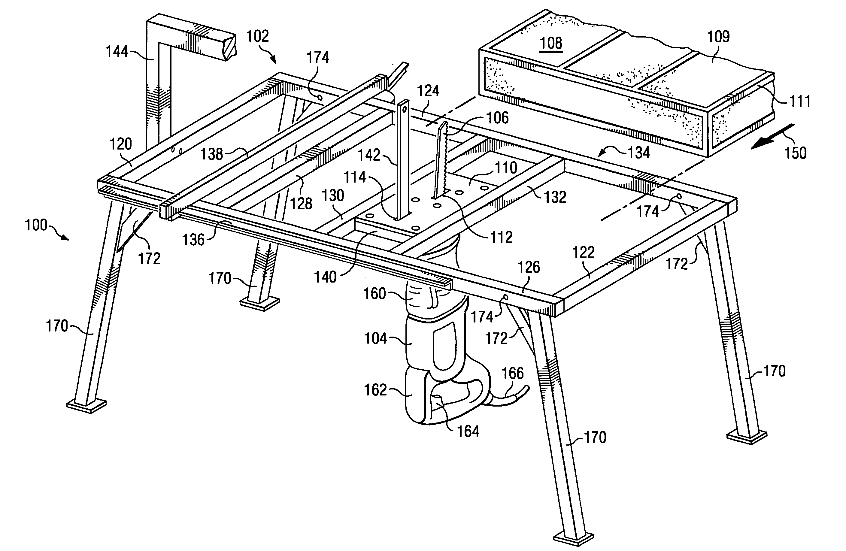
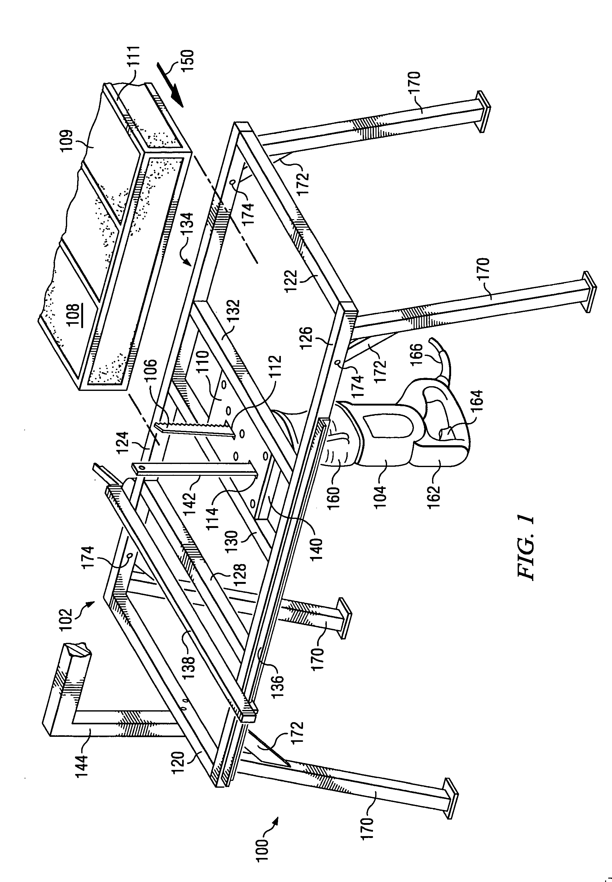
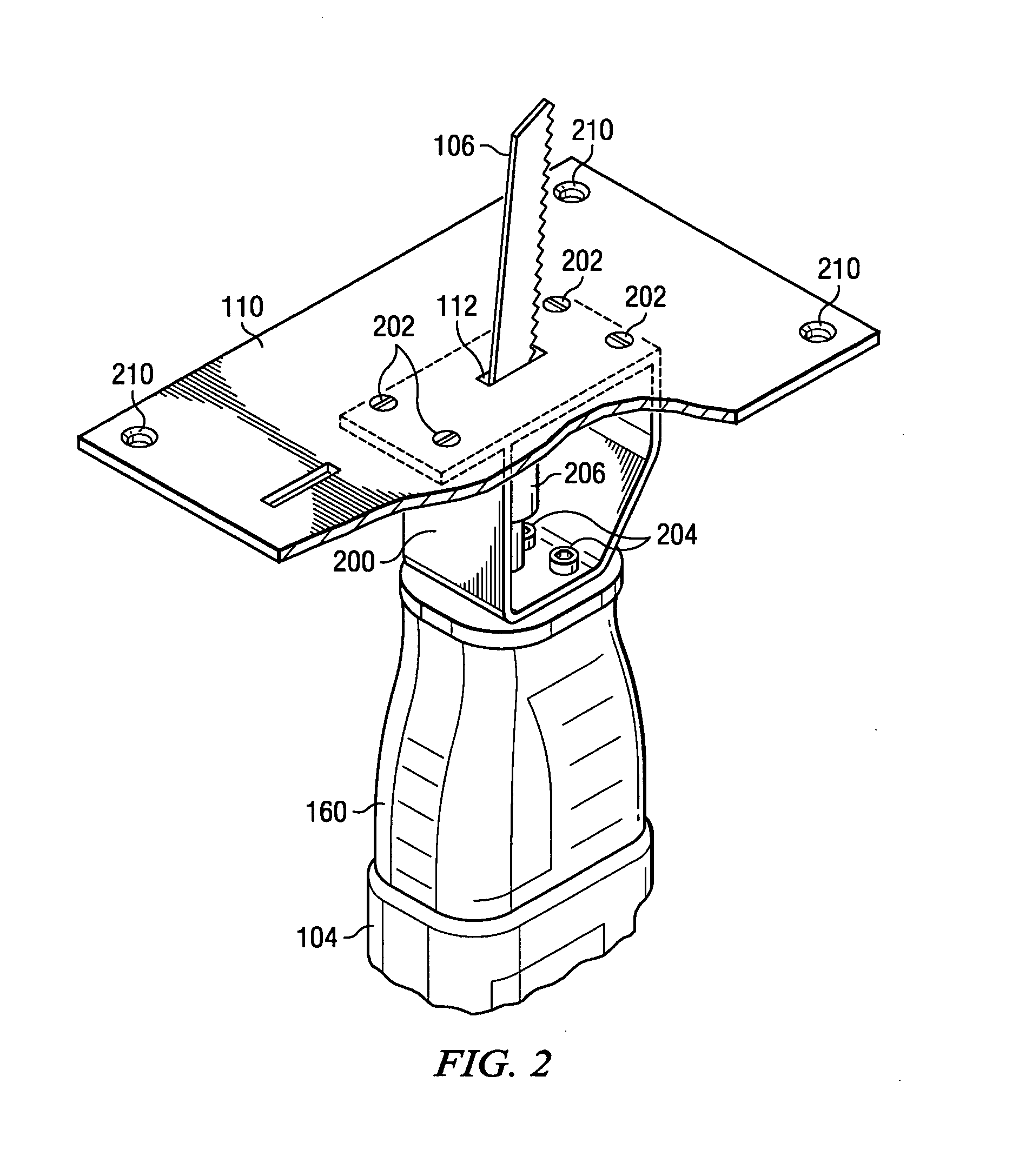
[0018] The powered reciprocating table saw of the present invention, while designed for cutting large foam / steel insulated building panels, embodies a versatility beyond that particular application because it functions much like a large band saw having the capacity for sawing large work pieces, and it may be used as a table saw that can saw curved cuts in a wide variety of materials. Unlike a conventional band saw, it is designed to be portable and easily set up on a work site. A pilot hole is not required as is necessary with a band saw when making inside cuts. It is safer to use than a table saw because the blade does not tend to pull the work piece into the blade. Although the preferred embodiment is constructed of aluminum for light weight, it is easy to construct from a variety of materials, and may be configured with folding legs or supported on saw horses at the work site. It will also be appreciated that the invention is not limited to a particular brand or type of reciproca...


PUM

PropertyMeasurementUnit
angleaaaaaaaaaa
angle of reciprocationaaaaaaaaaa
angleaaaaaaaaaa

Abstract

There is disclosed a powered reciprocating table saw, for sawing large foam panels having embedded steel framing members, comprising a work table for supporting a workpiece on a top side of the work table and having a blade opening disposed through the work table proximate a central portion thereof. A saw motor is supported underneath the work table, the saw motor having a reciprocating output shaft extending from a housing of the motor, and blade clamping means disposed on the output shaft. An elongated saw blade is retained in the blade clamping means of the saw motor and positioned to move reciprocatingly through the blade opening to the top side of the work table for sawing the workpiece. In another aspect a motor mount is disclosed for attaching the saw motor to the work table. In yet another aspect a blade guide supported by the work table is disclosed, which limits sideways and rearward displacement of the saw blade while sawing the workpiece.

Description

BACKGROUND OF THE INVENTION [0001] 1. Field of the Invention [0002] The present invention generally relates to power tools and, more particularly, to motor driven saws. [0003] 2. Description of the Prior Art [0004] Construction of residential and small business buildings has traditionally utilized wood framing and fiberglass or rock wool insulation to provide insulated walls, ceilings and roofs for the buildings. Newer materials and methods providing improved energy efficiency are replacing the fiberglass or rock wool insulation materials with foam products such as foam-in-place polyurethane or rigid panels fabricated from polystyrene. One type of panel, available from companies such as ThermaSteel, of Radford, Va. or Techbuilt Manufacturing, of Cleveland, Ohio, is constructed of molded polystyrene with steel framing members integrated within the panels during molding These foam / steel panels are available in various sizes, typically 2′×8,′ 4′×8′ or larger, and in thicknesses from 3-...

Claims


Application Information

Patent Timeline
Patent Type & Authority Applications(United States)
IPC IPC(8): B23D49/08B23D51/02B23D51/03B25H1/04B26D5/00
CPCB23D49/08B25H1/04B23D51/03B23D51/025Y10T83/8763Y10T83/8878Y10T83/95
Inventor RUE, JERRY RANDALL
Owner RUE JERRY RANDALL
Why Eureka
Try Eureka