
Flexible floor and a corridor connection including the floor

a flexible floor and floor technology, applied in the direction of transportation and packaging, substation equipment, railway bodies, etc., can solve the problems of lack of compactness, lack of protection, wear, etc., and achieve the effect of not providing any protection, and reducing the number of devices

Inactive Publication Date: 2005-08-25
HUTCHINSON SA
View PDF3 Cites 13 Cited by
  • Summary
  • Abstract
  • Description
  • Claims
  • Application Information

AI Technical Summary

Benefits of technology

[0007] An object of the present invention is to provide a flexible floor for a corridor connection which, while maintaining its properties as regards requirements due to displacements between the bodies of the cars, offers better noise attenuation and improved appearance.
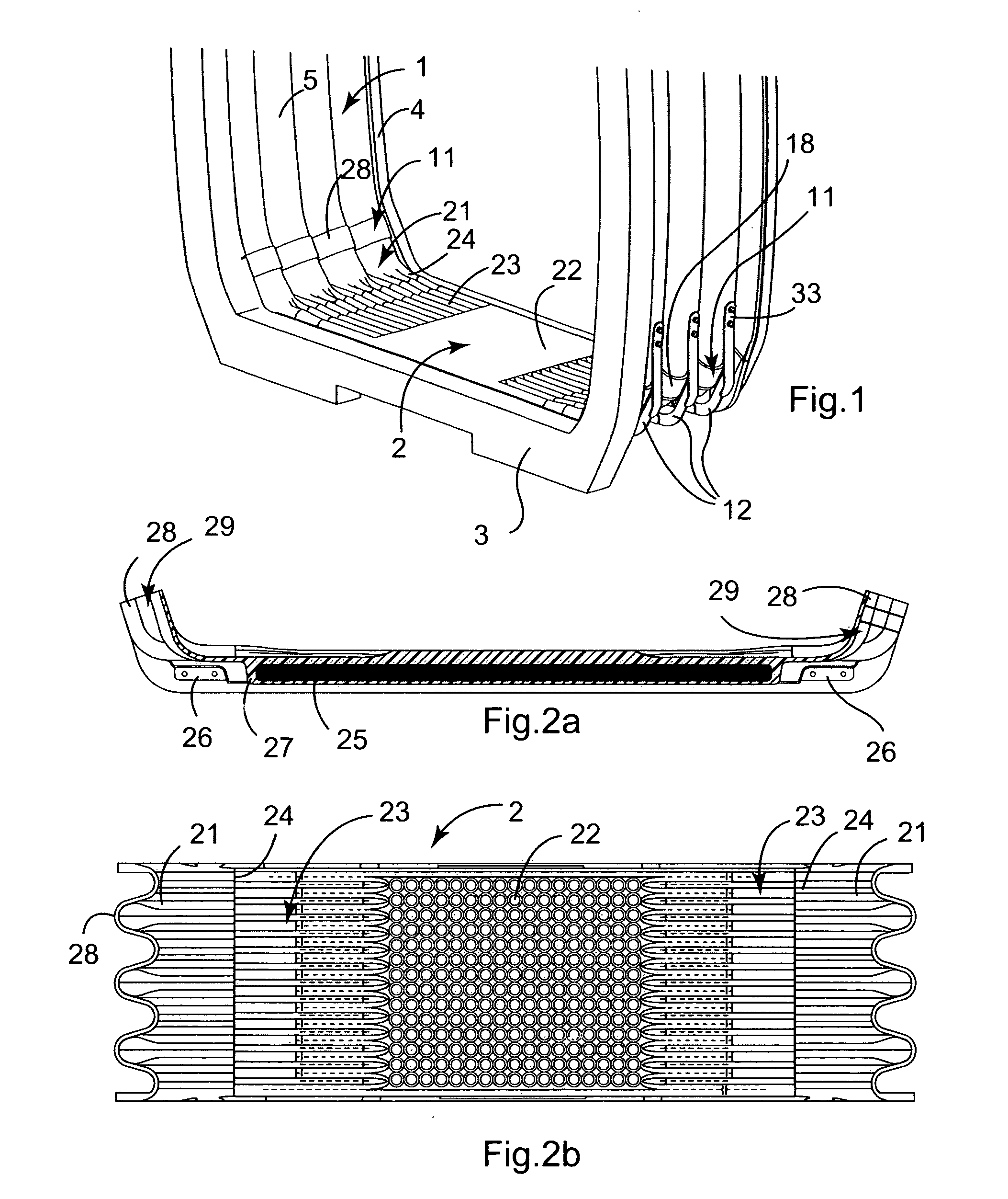
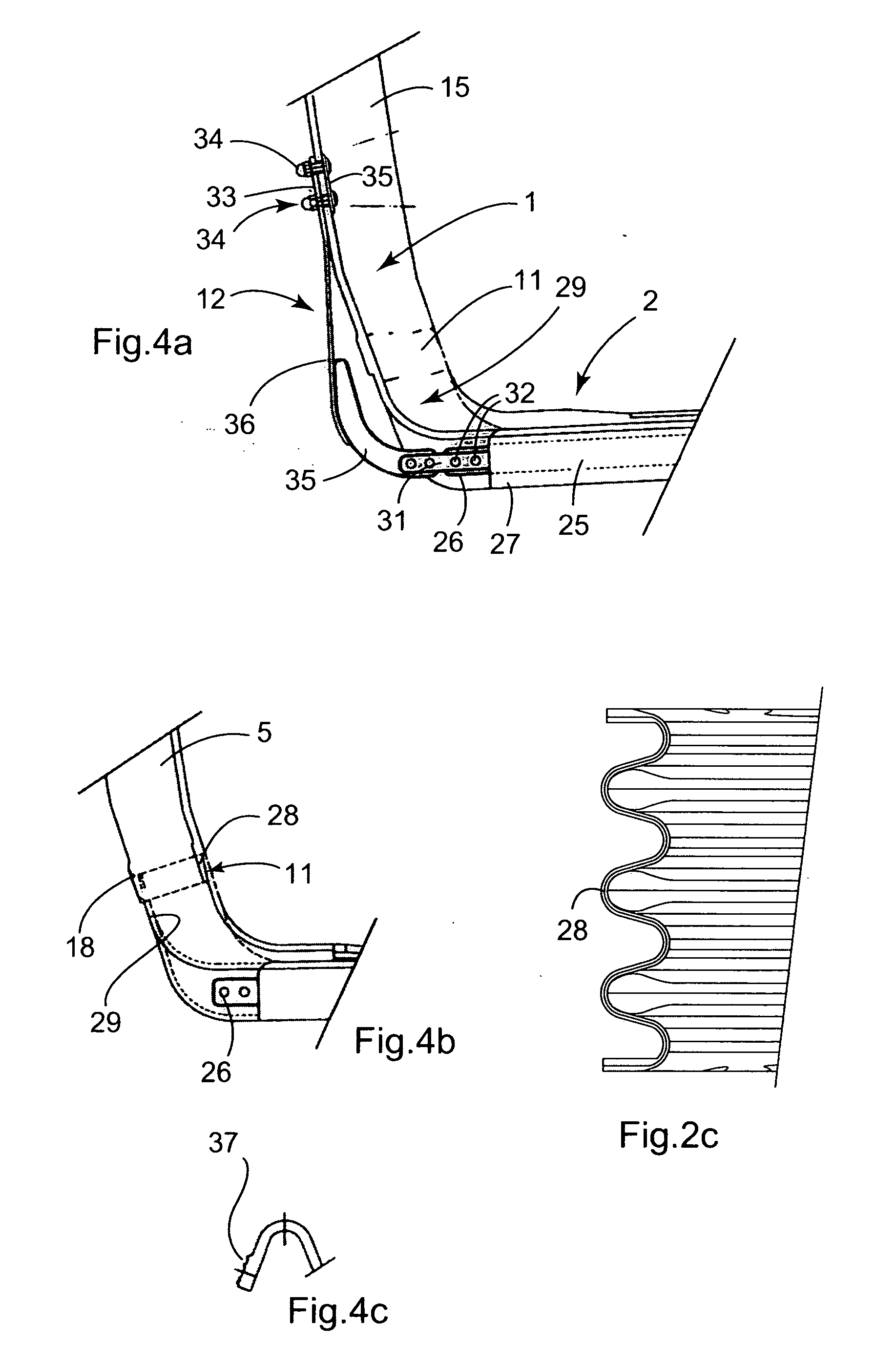
[0010] This structure thus makes it possible for the floor to be coupled mechanically to the bellows via the outside, independently of the coupling between the raised edges and the bellows, which coupling can be achieved easily in sealed manner and thus under good noise conditions since the mechanical function of supporting the floor no longer needs to be provided thereat.
[0011] In addition, the mechanical coupling to the bellows, implemented on the outside, and separately from the coupling between the raised edges of the floor and the bellows, also makes it possible, e.g. by means of fastening using bolts, to maintain good soundproofing qualities.
[0020] In known manner, the ends of a longitudinal module may be equipped with metal and / or composite parts making it possible to fasten said module to the body and / or to the coupling ring.

Problems solved by technology

Certain known devices require doors and do not provide any protection from cold and noise, while others use a system made up of a protective bellows and of a metal floor, with all the ensuing problems of metal slides and hinges in the floor.
Using such known devices is not without problems relating to maintenance, to wear, to noise, to lack of compactness, to cleaning, e.g. for draining cleaning water, or to cavities in which various objects can build up.
In addition to being visible, such a coupling suffers from the drawback of providing no sealing, and therefore of offering only a very small amount of noise attenuation at the coupling between the floor and the bellows.

Method used


Image

  • Flexible floor and a corridor connection including the floor
  • Flexible floor and a corridor connection including the floor
  • Flexible floor and a corridor connection including the floor

Examples


Embodiment Construction

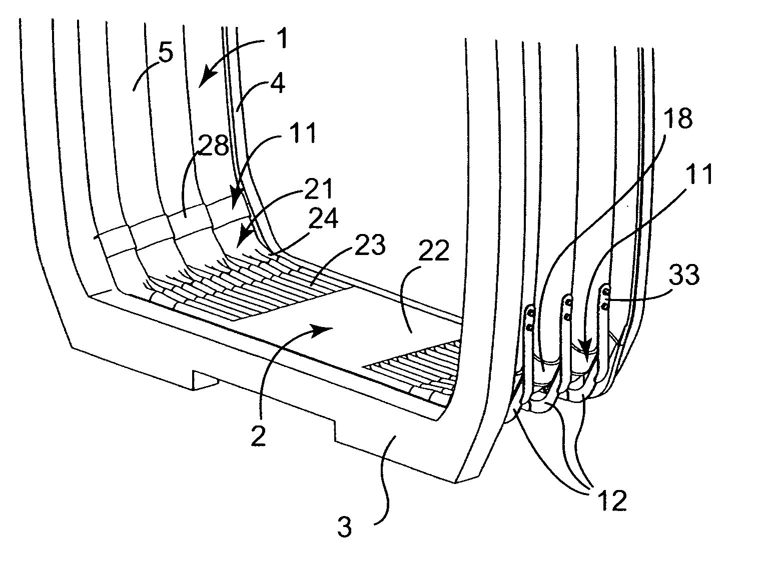
[0026] In known manner, a corridor connection bellows equipped with a flexible floor is made up of at least one corridor connection module, each such module having a top portion or deformable bellows 1 having undulating regions, and a bottom portion or floor 2. The bellows 1 and the floor are made from an elastomer mixture in which textile reinforcement elements can be embedded (for the bellows) and metal can be embedded that is caused to adhere to the mixture (for the floor).

[0027] The bellows 1 and the floor 2 are different pieces which are assembled together to form a corridor connection module which constitutes a structure having a closed perimeter and that is preferably self-supporting.

[0028] In corridor connections currently in existence (in particular on the METEOR Line in Paris), mechanical assembly is performed at the raised edges, which gives rise to constraints and to drawbacks: [0029] since the floor is supported by the bellows, the mechanical coupling can be provided ...


PUM


Abstract

The invention relates to a flexible floor designed to be suspended from an undulating flexible bellows in order to form a corridor connection module, said floor presenting undulating raised edges at its transverse ends, and, on its bottom face, transverse ribs in which metal reinforcements are embedded. According to the invention, at least some of the metal reinforcements have ends that project beyond the transverse ribs, each of which projecting ends is coupled to a fastening device for fastening the floor to the bellows, which fastening device extends alongside the outside of the corresponding undulating raised edge and presents a fastening end for fastening to the bellows that is situated above the corresponding raised edge.

Description

[0001] The present invention relates to a flexible floor designed for a gangway corridor connection for intercommunication between two cars, and more particularly designed for rail vehicles such as trains, subway trains, trams, etc., or more generally for any rail or non-rail moving assembly. The present invention also relates to a corridor connection including such a flexible floor. BACKGROUND OF THE INVENTION [0002] Certain known devices require doors and do not provide any protection from cold and noise, while others use a system made up of a protective bellows and of a metal floor, with all the ensuing problems of metal slides and hinges in the floor. [0003] Other devices require space to be dedicated to them in the ends of the bodies for the purpose of receiving the floor systems. [0004] Most devices require mechanical load take-up or load bearing systems, e.g. bearing on the coupling bar. Using such known devices is not without problems relating to maintenance, to wear, to noi...

Claims


Application Information

Patent Timeline
IPC IPC(8): B60D5/00B61D17/20B61D17/22
CPCB61D17/22B60D5/006H04M1/026
Inventor PETIT, JEAN-CLAUDEANTONIO, RICHARD DE
Owner HUTCHINSON SA
Learn More