Coolant tray of liquid based cooling device

a cooling device and liquid based technology, applied in the field of cooling devices, can solve the problems of limited heat removal of aluminum extrusion heat sinks, complicated assembly of cooling devices, and large volume of cooling devices, and achieve the effects of reducing overall size, reducing structure and manufacturing of cooling devices, and limited interior spa

Inactive Publication Date: 2005-08-25
CHENG RUEI FU +1
View PDF8 Cites 39 Cited by
  • Summary
  • Abstract
  • Description
  • Claims
  • Application Information

AI Technical Summary

Benefits of technology

[0011] Since three parts, including the housing of the coolant tray, the casing of the pump, and the conduit connected between the housing and the casing are integrally formed together with the same material as a single unitary member, the structure and manufacturing of the cooling device is simplified and the overall size reduced, making the cooling device in accordance with the present invention particularly suitable for portable electronic devices that have a very limited interior space for accommodation of the cooling device, while requiring efficient removal of heat.

Problems solved by technology

However, such an aluminum extrusion heat sink is subject to limitation in removing a great amount of heat.
Such an arrangement makes the assembling of the cooling device complicated for there are a great number of parts, including those pipes, which must be individually coupled to the coolant tray, the coolant pump, and the radiator.
In addition, such a great number of the parts makes the cooling device expensive in manufacturing and bulky in size, which is against the trend of down-cost and miniaturization of the computer or electronic industry and is thus not suitable for applications in portable devices.

Method used


Image

  • Coolant tray of liquid based cooling device
  • Coolant tray of liquid based cooling device
  • Coolant tray of liquid based cooling device

Examples


Embodiment Construction

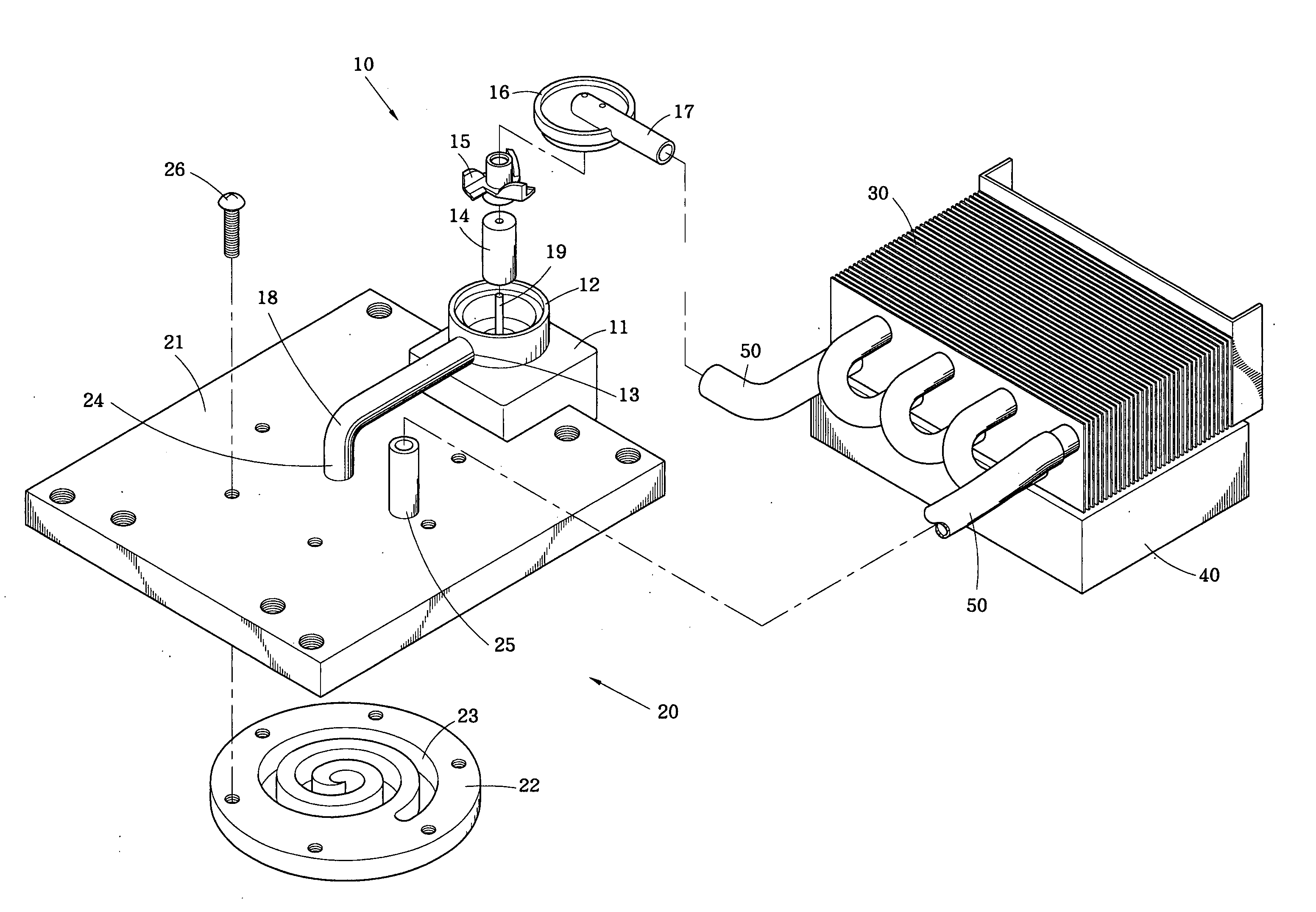
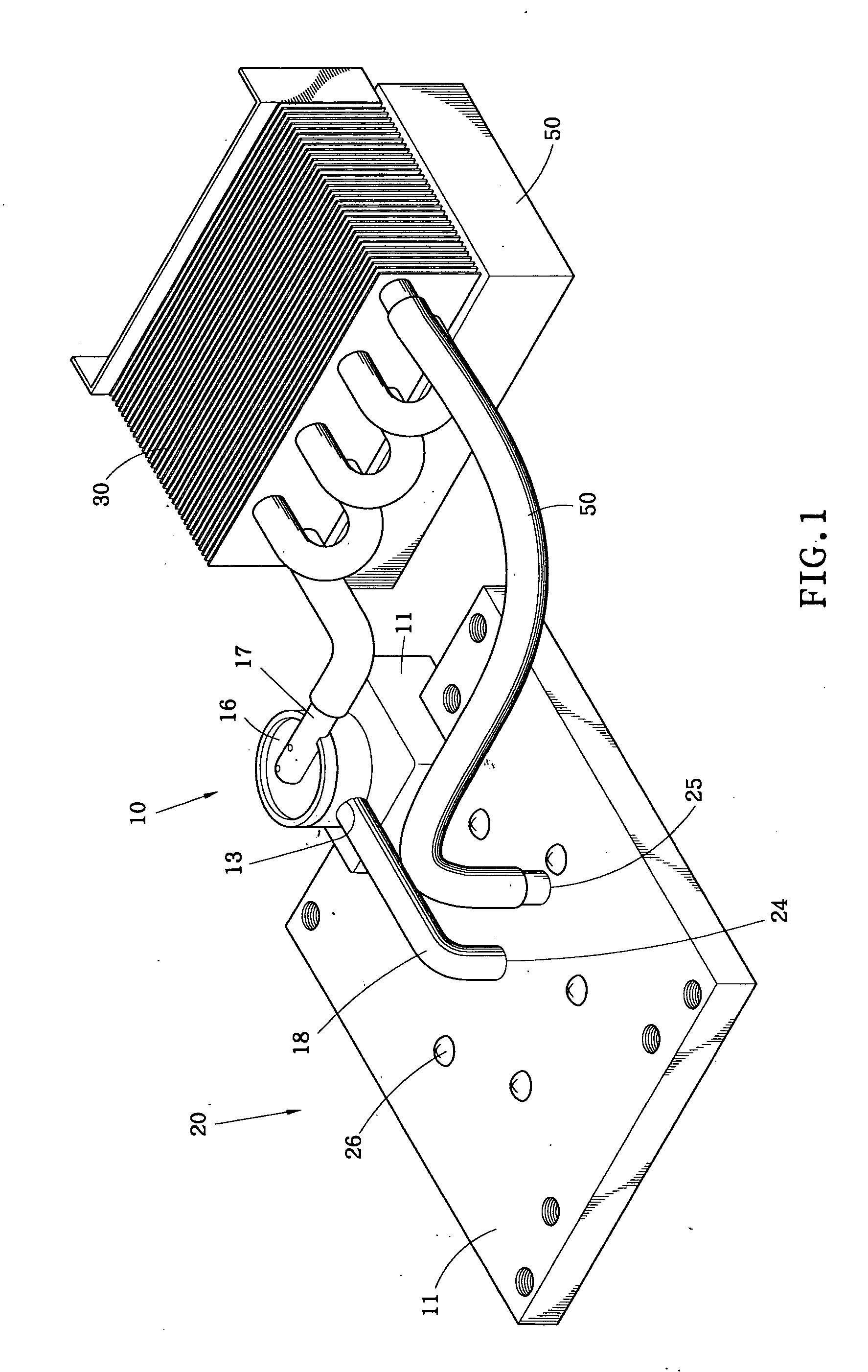
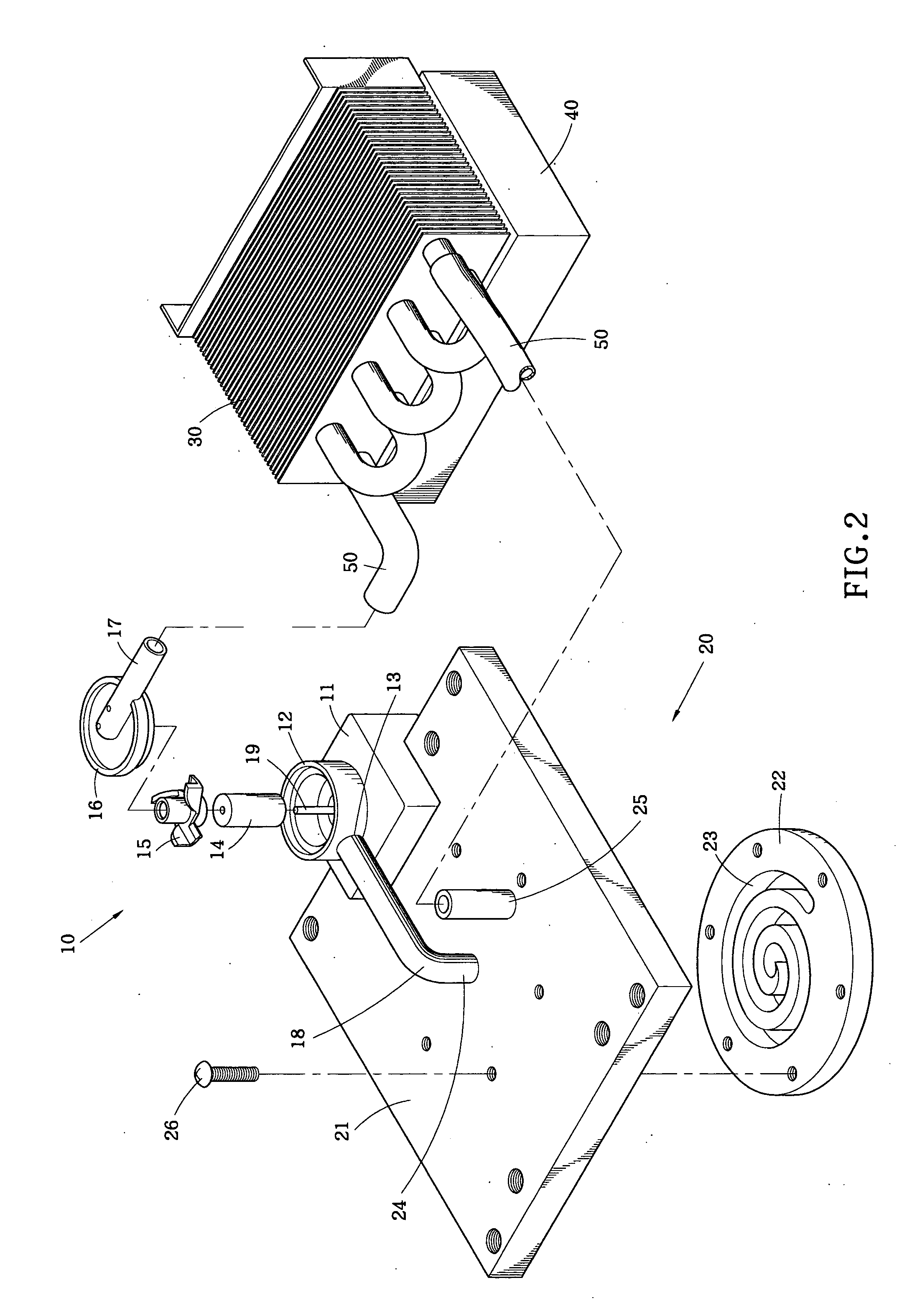
[0016] With reference to the drawings and in particular to FIG. 1, a liquid based cooling device is shown. The cooling device is operated with a liquid coolant, such as water, for cooling for example an electronic device 29, such as a computer central processing unit mounted on a circuit board 28 of the computer system (see FIG. 3), which generates heat that must be removed to maintain the temperature of the electronic device 29 within a proper range. The cooling device is comprised of a coolant tray 20 having a surface positionable on and in physical contact with the electronic device 29, a radiator 30 spaced from the coolant tray 20 and located in a low temperature surrounding, and a pump 10 connected to the radiator 30 and the coolant tray 20 by pipes to complete a circulation loop among the coolant tray 20, the pump 10, and the radiator 30. The pump 10 circulates a coolant between the coolant tray 20 and the radiator 30. Heat carried by the coolant to the radiator 30 is dissipat...


PUM


Abstract

A liquid based cooling device includes a pump for driving a coolant through a coolant tray that is positionable on a heat generating device and a radiator that dissipates the heat into the surrounding. The coolant tray includes a housing on which coolant inlet and outlet are formed for receiving the coolant from the pump and discharging the coolant to the radiator. The coolant tray also forms a recess in which a thermally conductive base forming a coolant channel is received in a liquid tight manner. The pump includes a casing in which coolant inlet and outlet are formed. The inlet of the coolant tray is integrally connected to the outlet of the pump and the housing of the coolant tray and the casing of the pump are integrally formed with each other with an integrally formed conduit connected therebetween. This simplifies the manufacturing of the cooling device and reduces the overall size of the cooling device.

Description

BACKGROUND OF THE INVENTION [0001] 1. Field of the Invention [0002] The present invention generally relates to a cooling device using a liquid, such as water, as coolant, for cooling particularly a computer system, and in particular to a coolant tray of the cooling device that is positionable on a heat generating device of the computer system for effectively and efficiently removing heat from the heat generating device with the coolant flowing through an internal channel of the coolant tray. [0003] 2. The Related Art [0004] Conventionally, a heat sink, such as an aluminum extrusion having spaced fins, is positioned on and in physical engagement with a heat generating device, such as a central processing unit, of a computer system for removing heat from and maintaining proper operation temperature of the central processing unit. Such a heat sink is an air-cooling device that removes heat from the central processing unit with airflows. However, such an aluminum extrusion heat sink is ...

Claims


Application Information

Patent Timeline
Patent Type & Authority Applications(United States)
IPC IPC(8): F28F3/12H01L23/473
CPCF28F3/12H01L23/473H01L2924/0002H01L2924/00
Inventor CHENG, RUEI-FUCHEN, TS'UNG CHIN
Owner CHENG RUEI FU
Why Eureka
Try Eureka