Optical device and projector
- Summary
- Abstract
- Description
- Claims
- Application Information
AI Technical Summary
Benefits of technology
Problems solved by technology
Method used
Image
Examples
first embodiment
[First Embodiment]
[0075] A first embodiment of the present invention will be described below with reference to the accompanying drawings.
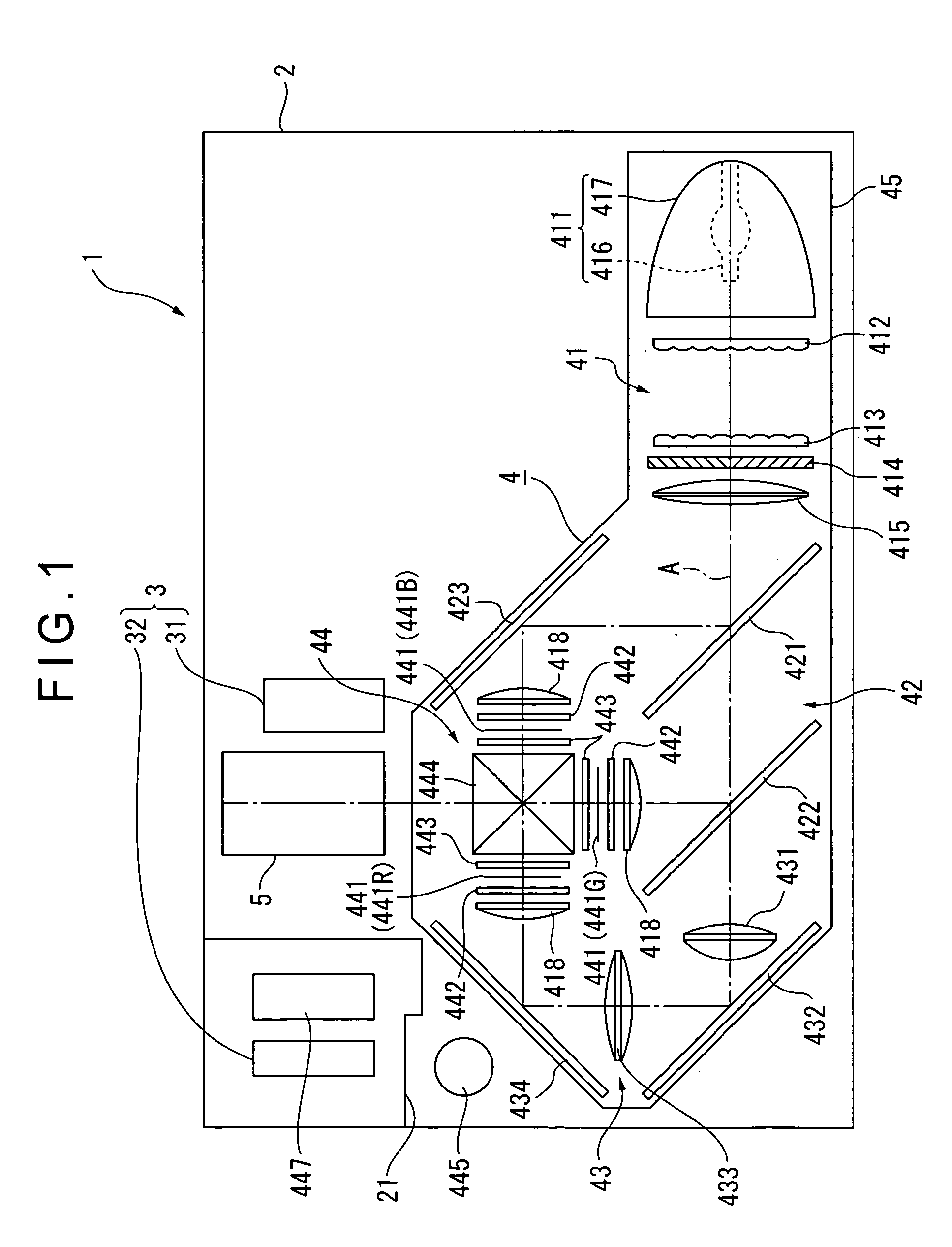
[0076]FIG. 1 is a view schematically showing a configuration of a projector 1.
[0077] The projector 1 modulates a light beam emitted from a light source in accordance with image information to form an optical image and projects the formed optical image on a screen in an enlarged manner. The projector 1 includes an outer case 2 serving as an outer casing, a cooling unit 3, an optical unit 4, and a projection lens 5 serving as a projection optical device.
[0078] In the outer case 2 of FIG. 1, although not shown, a power block, a lamp drive circuit and the like are arranged in the space other than the portions occupied by the cooling unit 3, optical unit 4, and projection lens 5.
[0079] The outer case 2 is formed of synthetic resin and the like and is formed in substantially a rectangular solid shape as a whole inside which the cooling unit 3, optica...
second embodiment
[Second Embodiment]
[0214] A second embodiment of the present invention will next be described with reference to the accompanying drawings.
[0215] In the following description, the same reference numerals as those in the first embodiment denote the same structures and components as those in the first embodiment, and the detailed descriptions thereof are omitted or simplified.
[0216] In the first embodiment, the outlet valve 4491B of the replenishment tank 449 is moved by the valve guide section 4454C of the main tank 445 to open the outlet hole 4491A in the closed state. The replenishment tank 449 has no mechanism to allow the position of the outlet valve 4491B to be set back to the position at which the outlet hole 4491A is in a closed state from the open position of the outlet hole 4491A.
[0217] On the other hand, in the second embodiment, a replenishment tank 549 has a mechanism to allow the position of an outlet valve 5491B to be set back to the position at which a cooling fluid ...
third embodiment
[Third Embodiment]
[0232] A third embodiment of the present invention will next be described with reference to the accompanying drawings.
[0233] In the following description, the same reference numerals as those in the first embodiment denote the same structures and components as those in the first embodiment, and the detailed descriptions thereof are omitted or simplified.
[0234] In the first embodiment described above, the replenishment tank 449 is attached to the main tank 445 when the main tank 445 needs to be replenished with a cooling fluid.
[0235] On the other hand, in the third embodiment, a cooling fluid inlet section 6454 is formed so that a main tank 645 can be replenished with a cooling fluid, which eliminates the need for the replenishment tank 449. It is assumed that the configurations of the components other than the main tank 645 are the same as those in the first embodiment.
[0236]FIG. 14 is a perspective view showing a structure of the main tank 645 according to the...
PUM
 Abstract
Description
Claims
Application Information
 - R&D
- Intellectual Property
- Life Sciences
- Materials
- Tech Scout
- Unparalleled Data Quality
- Higher Quality Content
- 60% Fewer Hallucinations
Browse by: Latest US Patents, China's latest patents, Technical Efficacy Thesaurus, Application Domain, Technology Topic, Popular Technical Reports.
© 2025 PatSnap. All rights reserved.Legal|Privacy policy|Modern Slavery Act Transparency Statement|Sitemap|About US| Contact US: help@patsnap.com


