
Laser instrument

a laser and beam technology, applied in the direction of instruments, optical elements, optical radiation measurement, etc., can solve the problems of inability to overcome this factor, the strength of each of the plurality of beams may become too low to be of practical use, and the target may be too weak to see clearly, so as to improve the utility of the instrument, reduce the power of the single beam, and enhance the power

Inactive Publication Date: 2005-08-25
WHITE BOX
View PDF8 Cites 4 Cited by
  • Summary
  • Abstract
  • Description
  • Claims
  • Application Information

AI Technical Summary

Benefits of technology

[0006] It is a first object of the invention to provide an improvement, to laser beam projection instruments having provision for projecting a single, e.g. axial, beam; and for dividing that single beam into a plurality of beams, by which the relative power of the single beam, and of the plurality of beams, can be varied so that the power of the multiple beams can be increased while still remaining within acceptable limits.
[0007] It is a second object of the invention to provide an improvement, in laser beam projection instruments, whereby the power of the single beam is variable at its stage of generation such that its power may be at an acceptable level while the single beam is being used, and may be increased when a plurality of beams are produced, to enhance the utility of the instrument at a distance from a target, while nevetheless keeping the power of the plural beams at acceptable level.
[0008] It is a third object of the invention to provide an improvement, in laser beam projection instruments, whereby the power of the single beam is made initially substantially higher than would be safe if used alone so as, when it is sub-divided into a plurality of beams, to permit that plurality of beams each to have a usefully enhanced power, and whereby the power of the single beam is reduced by attenuation, when used as a single beam, so as to remain within acceptable limits.

Problems solved by technology

According to the degree of sub-division of the single beam, the strength of each of the plurality of beams may then become too low to be of practical use, i.e. the illumination provided by each of them on the surface of the target may be too weak to see clearly, especially in bright ambient light or at a relatively long distance which may be essential in the investigation of a target surface which is at a very high temperature.
It is not possible to overcome this factor of change of intensity, as between the single beam and the plurality of beams by merely increasing proportionately the power of the single beam when it is to be subdivided, because there are legal and practical restrictions on the use of laser beams because of the possible danger to the user, e.g. the damaging of eyesight.
Unless provision can be made for changing of the strength of the laser beam, there is always a limitation of (a) the number of beams which can usefully be obtained from splitting of a single beam, and (b) the effectiveness of the instrument, used with a distant target, because of the resultant relatively lowered illuminating power of each of the beams which is split from the original single beam.

Method used


Image

  • Laser instrument
  • Laser instrument
  • Laser instrument

Examples


Embodiment Construction

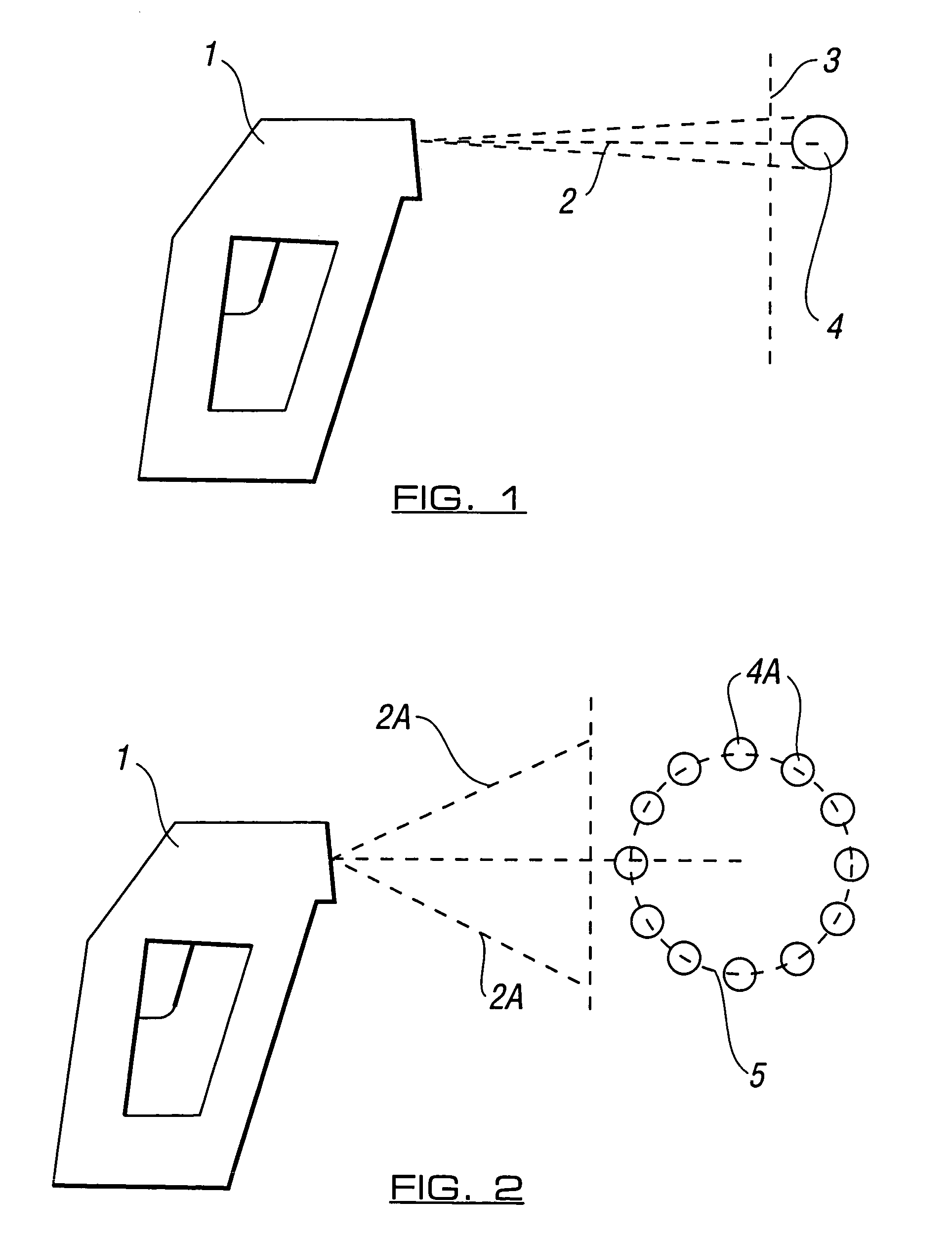
[0015] Referring to FIG. 1 of the drawings there is shown a radiometer instrument 1 incorporating a laser beam production means which produces a single axial laser beam 2 which is directed at a target 3 and produces on the target an illuminated spot 4.

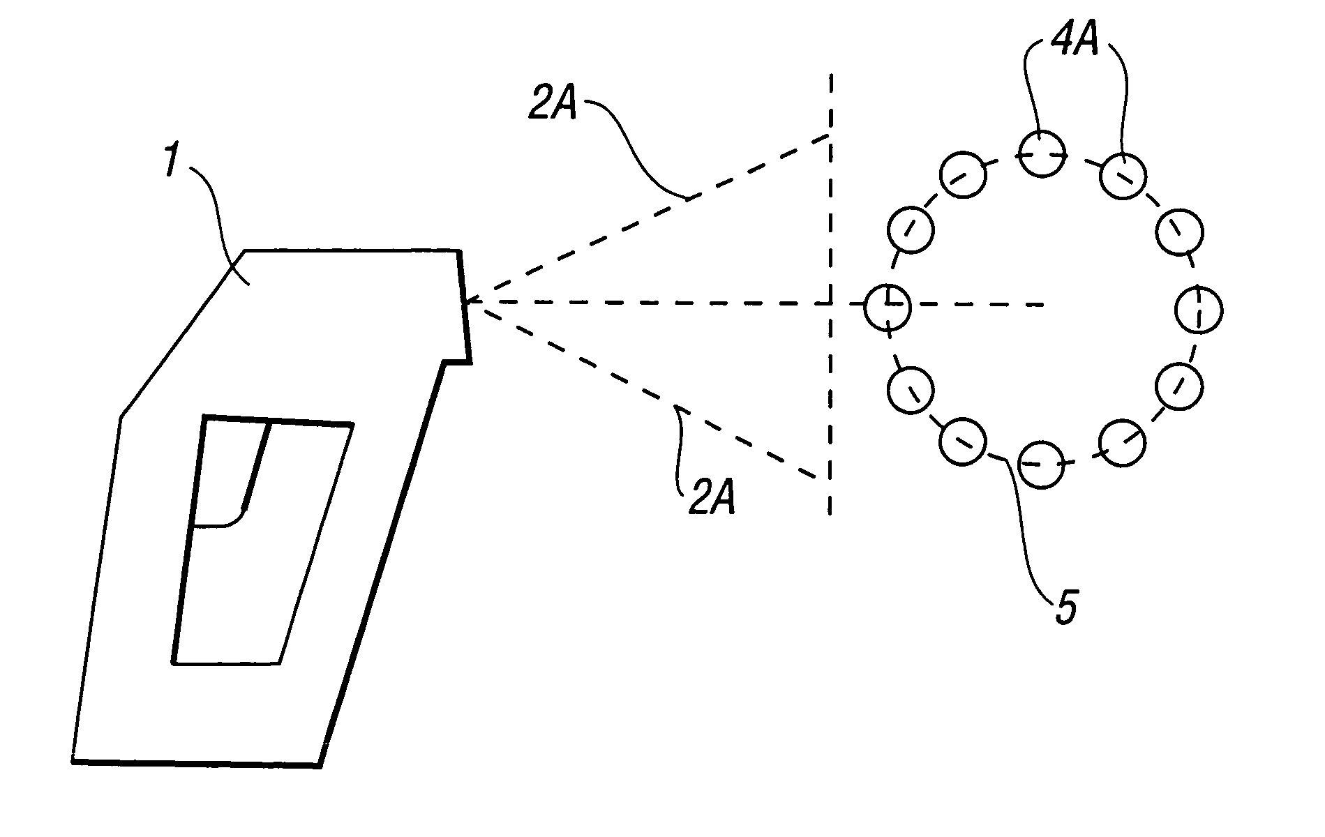
[0016] Referring to FIG. 2 of the drawings there is shown the same radiometer instrument in an alternative manner of operation in which it produces a plurality of beams 2A which produce on the target a plurality of spots 4A arranged in a circle to define an area 5.

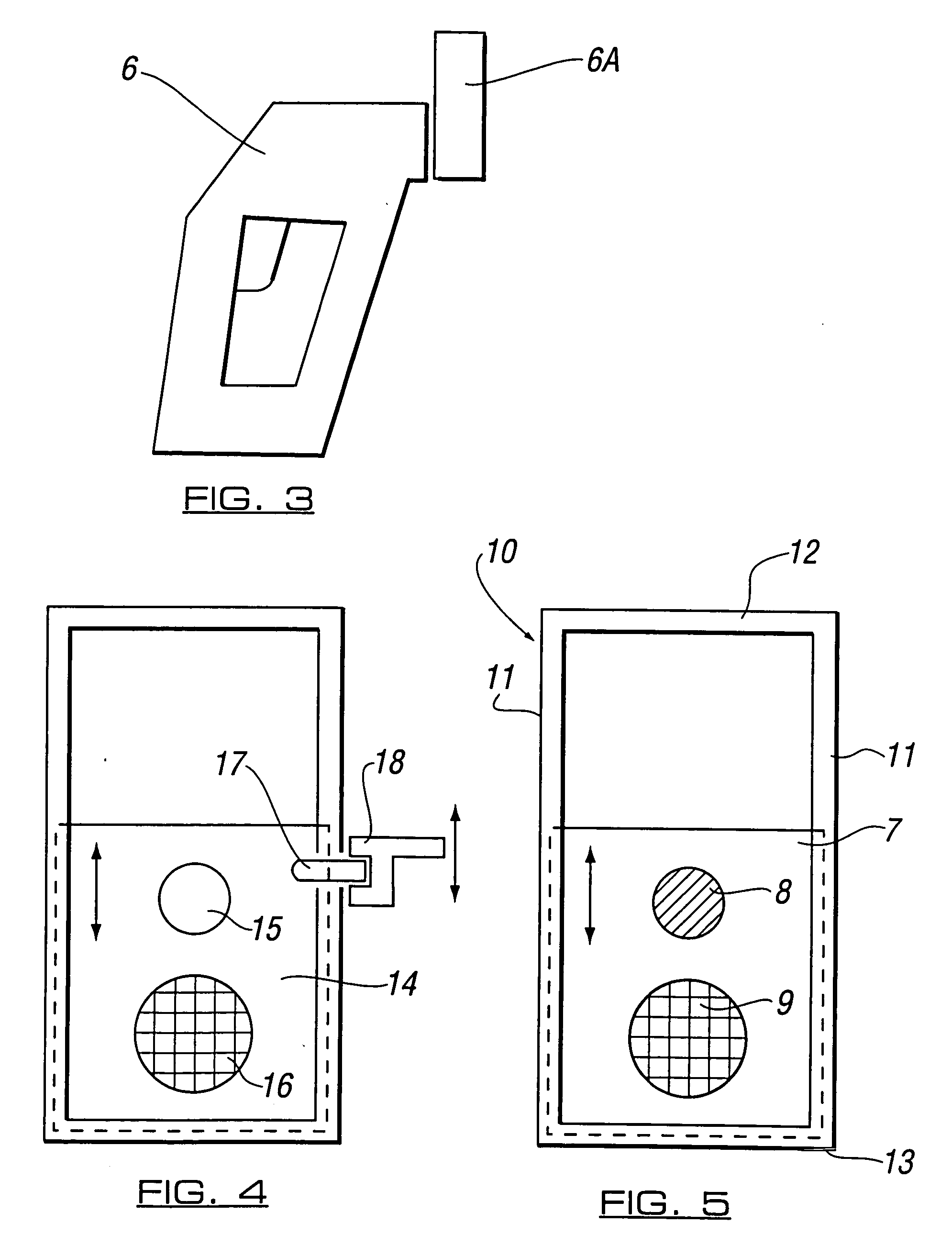
[0017] Referring to FIG. 3 of the drawings there is shown a further embodiment 6 of radiometer instrument which has at its front end a demountable attachment 6A which is adjustable, in the manner described below with reference to FIGS. 4 and 5, to produce selectively a single axial laser beam and a plurality of spaced laser beams for defining an area of a target.

[0018] Referring to FIG. 4 of the drawings, the attachment in a preferred embodiment of the best known mode inco...


PUM


Abstract

The invention relates to instruments, such as radiometers, which generate a laser beam for striking a target at a distance to assist in aiming the instrument at a selected area of a target. Provision is made for splitting a single beam, used for instance for centering the instrument on the target, into a plurality of beams for creating a pattern or for defining an area on the target. When a single beam is split, the resultant plural beams produced are of relatively lower power, which may be insufficient for visibility on a target at a distance. In a first embodiment the invention provides apparatus to increase the power of the single laser beam when it is split, so as to provide plural beams of appropriately higher power and visibility. In a second embodiment, the invention provides apparatus for attenuating the beam power when a single beam is used, and for removing the attenuation when the beam is split into multiple beams. Apparatus for changing the single beam of the instrument to multiple beams, and vice versa, has a body structure with a relatively movable carrier incorporating a beam splitter device, and an attenuating or non-attenuating device, such that relative movement of the carrier causes, in a first embodiment, an increase of the laser beam power when only a single beam is used, and in a second embodiment an attenuation of the laser beam power when a relatively higher power single beam is used. In the second embodiment, the relative movement of the carrier serves to actuate switching means controlling the power of the laser beam. Such apparatus is advantageously in the form of an attachment for engagement releasably on the laser beam instrument.

Description

FIELD OF THE INVENTION [0001] The present invention relates generally to the projection of laser beams for the directional aiming of apparatus such as radiometer instruments, which may be used for ascertaining the temperature of a surface using infra-red measurement techniques, and more particularly to such apparatus which utilises a laser sighting device arranged to project one or more laser sighting beams onto a target for identifying on the surface of the target an energy zone thereof, the temperature of which is to be measured. [0002] It is useful, in the operation of such laser beam projection apparatus, to have the facility to change the number and / or configuration of beams which are issued from the laser beam projector. [0003] By way of example, in a first case it may be desirable to have a single beam which is axial and which gives rise to a single central illuminated spot on the target area to be investigated. In a second case it may be desirable to have a plurality of lase...

Claims


Application Information

Patent Timeline
Patent Type & Authority Applications(United States)
IPC IPC(8): G01J5/08G02B23/00G02B23/04G02B27/10G02B27/20
CPCG01J5/0265G01J5/08G01J5/0812G01J5/0831G01J5/084G01J5/089G02B27/20G02B23/00G02B23/04G02B27/106G02B27/108G02B27/1093G02B27/123G01J5/0896G01J5/0816G01J5/07
Inventor HOLLANDER, MILTON BERNARD
Owner WHITE BOX
Learn More