Diaphragm-based reservoir for a closed blood sampling system

a technology of diaphragm and reservoir, which is applied in the field of closed blood sampling systems, can solve the problems of reservoir contents escaping from the leakage path, potentially harming the patient, and the source of potential leakage or contamination paths

Inactive Publication Date: 2005-08-25
SMITHS MEDICAL ASD INC
View PDF99 Cites 45 Cited by
  • Summary
  • Abstract
  • Description
  • Claims
  • Application Information

AI Technical Summary

Benefits of technology

[0043] Another advantage of the present invention is that as the reservoir volume expands and collapses, the outer edge of the flexible membrane remains securely sealed to the lower housing, and so does not slide along either the lower or upper housing wall. Because the seal created at the edge of the flexible membrane and the rigid wall is fixed, there is no potential leak path for blood and other bio-hazardous fluids to escape to the environment. Moreover, there is also no contamination path for bacteria or other contaminants to enter the bloodstream.

Problems solved by technology

Such sealing members slide along the cylinder side and can be a source of potential leakage or contamination paths.
Failure of the seal creates a leakage path for reservoir contents to escape to the environment.
In some cases, this pulling might create a sufficient pressure drop to collapse a patient's artery thereby preventing a blood sample and, more importantly, potentially harming the patient.
Such pulling could also de-gas the blood potentially causing inaccurate blood gas values in the sample.
Either could happen, for example, if the piston were pulled too quickly.
The proper rate at which to retract the piston then becomes problematic, depending on such factors as the size of the artery and the age of the particular patient.

Method used


Image

  • Diaphragm-based reservoir for a closed blood sampling system
  • Diaphragm-based reservoir for a closed blood sampling system
  • Diaphragm-based reservoir for a closed blood sampling system

Examples


Embodiment Construction

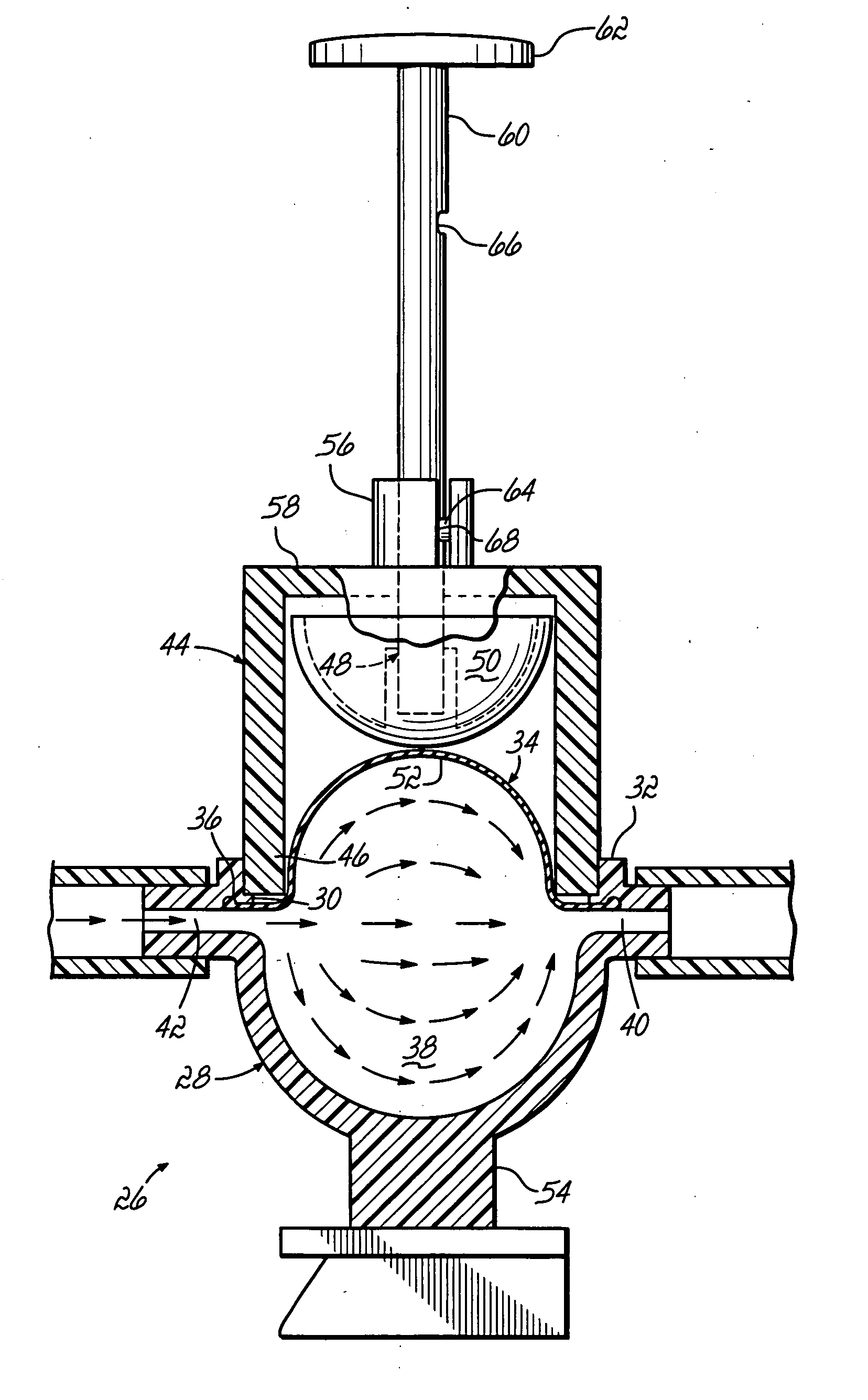
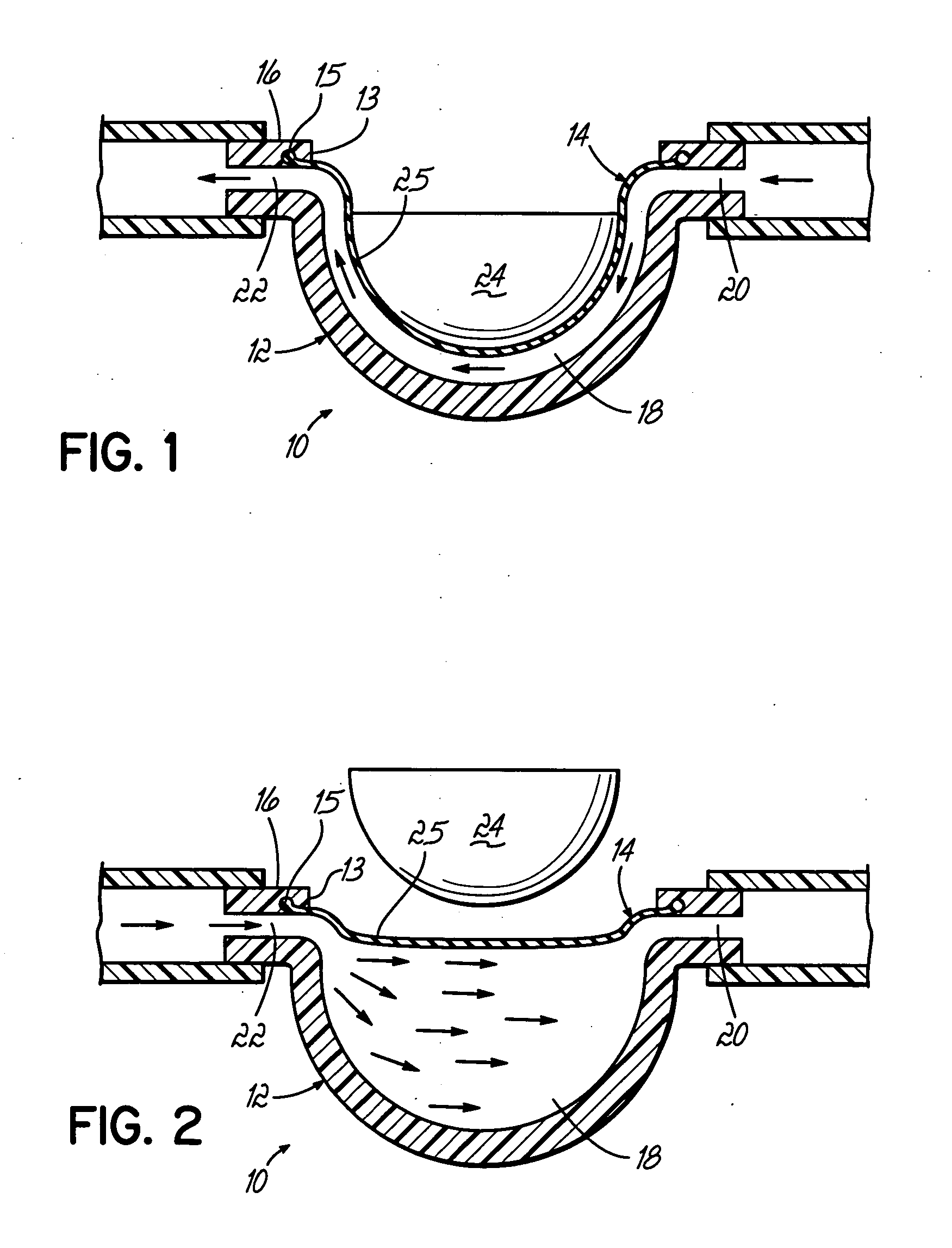
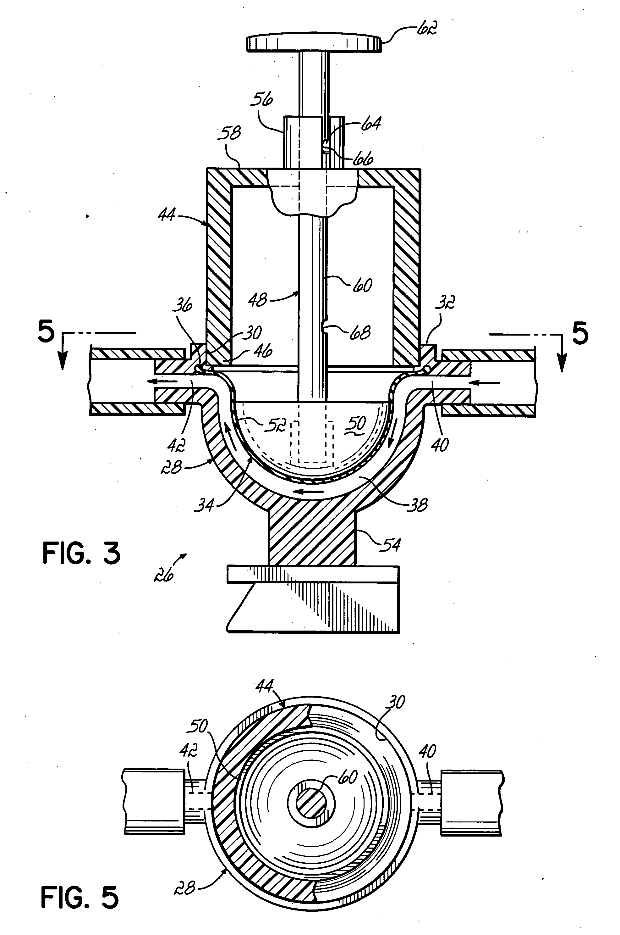
[0026] With reference to FIGS. 1-2, there is shown a simplified embodiment of a diaphragm-based reservoir 10 for a closed blood sampling system in accordance with the principles of the present invention. Reservoir 10 is defined by a rigid wall or lower housing 12 having an opening 13 and a flexible membrane 14 sealed to the opening periphery, such as by fixedly securing membrane 14 along its outer edge 15 to an upper edge 16 of rigid wall 12 to close off opening 13 and define an internal chamber 18. Reservoir 10 further includes fluid inlet and exit ports 20, 22 respectively in fluid communication with chamber 18 to allow fluid and / or blood to flow in or through the chamber. As shown in FIG. 1, the membrane 14 has a minimum volume position where the membrane 14 is spaced closely adjacent the rigid wall 12 to define a minimum volume of the chamber 18 such that fluid may still flow between inlet and exit ports 20, 22 and through chamber 18. To keep the membrane 14 in the minimum volum...


PUM


Abstract

A reservoir (10, 26, 80, 126, 226, 380) includes a rigid wall (12, 28, 82, 128, 228, 382), a flexible membrane (14, 34, 134, 234, 334) sealingly secured to the rigid wall (12, 28, 82, 128, 228, 382) to define a variable volume chamber (18, 38, 138, 238, 338), and inlet (40, 140, 240, 340) and exit (42, 142, 242, 342) ports in fluid communication with the chamber (18, 38, 138, 238, 338). A drive surface (24, 50, 150, 250, 350) engages the membrane (14, 34, 134, 234, 334) to position it adjacent the rigid wall (12, 28, 82, 128, 228, 382) to define a minimum volume position. The drive surface (24, 50, 150, 250, 350) may be moved so that the membrane (14, 34, 134, 234, 334) flexes out of the minimum volume position to an expanded volume position. The membrane (14, 34, 134, 234, 334) may be coupled to the drive surface (24, 50, 150, 250, 350) or be uncoupled from the drive surface (24, 50, 150, 250, 350). The reservoir (10, 26, 80, 126, 226, 326) may be included in a closed blood sampling system (88) for drawing a sample of whole blood.

Description

FIELD OF THE INVENTION [0001] The present invention relates to closed blood sampling systems through which blood may be drawn from a patient, and more specifically, to an improved fluid storage device useful in facilitating the drawing of whole blood from a patient. BACKGROUND OF THE INVENTION [0002] In certain medical situations, such as coronary intensive care, highly accurate and real-time blood pressure monitoring is often required. Systems that provide this type of blood pressure monitoring are known and include a catheter, usually inserted into an artery of the patient's circulatory system, a pressure sensor for measuring the arterial pressure, and a length of tubing between the catheter and the pressure sensor. To keep the tubing patent, so that the pressure in the tubing is approximately the pressure in the patient's artery, a fluid supply is coupled through the pressure sensor through another length of tubing so that the fluid supply is in fluid communication with the patie...

Claims


Application Information

Patent Timeline
Patent Type & Authority Applications(United States)
IPC IPC(8): A61B5/15
CPCA61B5/1405A61B5/15003A61B5/150221A61B5/150229A61B5/150236A61B5/150244A61B5/150946A61B5/150992A61B5/153A61B5/155
Inventor THURAU, BERNDHERZ, ROBERTCRALL, ANGELAGALLOGLY, DALE
Owner SMITHS MEDICAL ASD INC
Why Eureka
Try Eureka