Tissue distraction device

a distraction device and tissue technology, applied in the field of surgery, can solve the problems of difficult to consistently achieve meaningful height restoration, increase the risk of bone filler extravasation from the vertebral body, and require extensive rehabilitation, so as to prevent the retrograde movement of the wafer

Active Publication Date: 2005-08-25
SPINEWAVE
View PDF20 Cites 152 Cited by
  • Summary
  • Abstract
  • Description
  • Claims
  • Application Information

AI Technical Summary

Benefits of technology

[0019] In certain embodiments, the wafer insertion apparatus includes a dual track assembly mounted to the advancement gun assembly. The dual track assembly includes a top track and a bottom track with a wafer “stay” that prevents retrograde motion of a wafer on the way to the distraction site. The top track serves as a carrier for traversing a series of wafers from the cartridge to a delivery or discharge end of the track assembly. The bottom track accepts an individual wafer from the top track at an introduction end of the track assembly and place that wafer in proper position before being advanced or pushed into the distraction site. Wafer stays hold the position of wafers in transit within the track assembly as the pusher and advancing mechanisms are retracted for a subsequent firing.
[0023] The present invention provides an apparatus for sequentially inserting wafers into a body space that incrementally advances the wafers to be discharged into the body space. One benefit of the invention is that it prevents retrograde movement of the wafers as they are advanced toward the body space. A further benefit is that the wafers can be provided in a removable and replaceable cartridge without disturbing the apparatus or its engagement with the body space.

Problems solved by technology

However, such conditions dramatically increase the risk of bone filler extravasation from the vertebral body.
However, it is difficult to consistently attain meaningful height restoration.
It appears the inconsistent results are due, in part, to the manner in which the balloon expands in a compressible media and the structural orientation of the trabecular bone within the vertebra.
Both of these methods are very invasive and require extensive rehabilitation.
Overall, the use of interbody devices has resulted in mixed clinical outcomes.
Placement of a fixed height device presents challenges in proper tensioning of the annulus.

Method used


Image

  • Tissue distraction device
  • Tissue distraction device
  • Tissue distraction device

Examples


Embodiment Construction

[0046] For the purposes of promoting an understanding of the principles of the invention, reference will now be made to the embodiments illustrated in the drawings and described in the following written specification. It is understood that no limitation to the scope of the invention is thereby intended. It is further understood that the present invention includes any alterations and modifications to the illustrated embodiments and includes further applications of the principles of the invention as would normally occur to one skilled in the art to which this invention pertains.

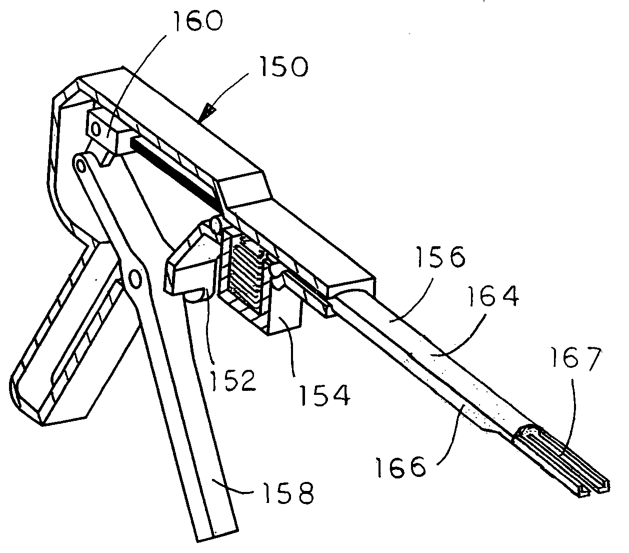
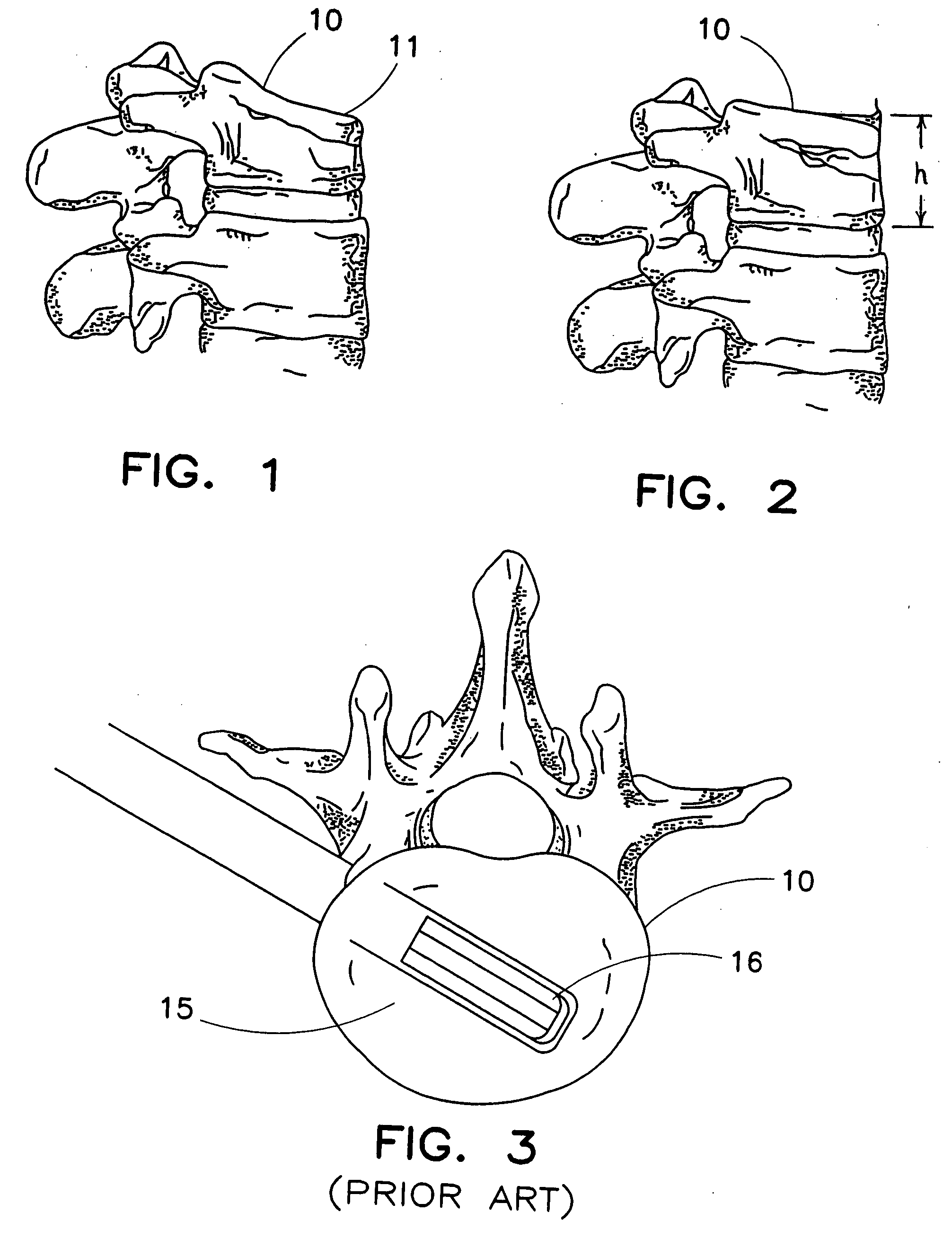
[0047] The invention provides a combination of an implantable distraction device and instrumentation to place the device. The distraction device is detailed in this section by its application to the vertebral compression fracture. FIG. 1 shows a vertebral body 10 having a compression fracture displacing its superior and anterior edge 11. FIG. 2 shows a vertebral body 10 wherein the height has been restored.

[0...


PUM


Abstract

An apparatus and method for distracting, in a given direction, and supporting two tissue surfaces is provided. A plurality of wafers are consecutively inserted between the two tissue surfaces to create a column of wafers. The column of wafers is oriented between the tissue surfaces so as to expand in the given direction as the wafers are consecutively added to the column. A wafer insertion apparatus includes a wafer cartridge configured to carry a stack of wafers to be inserted into the space, a track assembly including a first track for carrying a wafer toward the space, a second track and means for preventing retrograde movement of a wafer within the first track, an advancer / pusher mechanism slidably disposed within the second track and operable on a wafer within the first track to advance the wafer along the first track, and an advancement gun supporting the wafer cartridge and track assembly and having a trigger operably coupled to the advancer / pusher mechanism to propel the mechanism along the second track.

Description

REFERENCE TO RELATED APPLICATION [0001] This application claims priority to co-pending provisional application No. 60 / 459,036, filed on Mar. 31, 2003, in the name of the present inventors. The disclosure of this provisional application No. 60 / 459,036 is incorporated herein by reference.FIELD OF THE INVENTION [0002] The present invention involves the field of surgery, and particularly to the field of orthopaedic surgery, surgical instruments and methods of using the same. The invention has particular application in distracting and supporting tissue surfaces, such as bone surfaces. BACKGROUND OF THE INVENTION [0003] A variety of physical conditions involve two tissue surfaces that, for treatment of the condition, need to be distracted from one another and then supported away from one another. Such distraction may be to gain exposure to select tissue structures, to apply a therapeutic pressure to select tissues, to return tissue structures to their anatomic position and form, or in som...

Claims


Application Information

Patent Timeline
Patent Type & Authority Applications(United States)
IPC IPC(8): A61BA61B17/58A61B17/88
CPCA61B17/8852
Inventor RAYMOND, SPANKY A.BONO, FRANK S.WILSON, THOMAS G.LOGAN, JOSEPHWYSOCKI, STEVEN J.
Owner SPINEWAVE
Why Eureka
Try Eureka