Occupant restraint system

a technology for occupants and restraints, applied in pedestrian/occupant safety arrangements, instruments, tractors, etc., can solve the problems of large amount of electric power consumed for communication, and cpu always bears a heavy load of arithmetically processing

Inactive Publication Date: 2005-08-25
DENSO CORP
View PDF15 Cites 22 Cited by
  • Summary
  • Abstract
  • Description
  • Claims
  • Application Information

AI Technical Summary

Benefits of technology

[0032] Therefore, a start timing of outputting the acceleration signal can be reliably set.

Problems solved by technology

As a result, a problem arises that a large amount of electric power is consumed for the communication between the airbag ECU and the satellite sensor.
Therefore, another problem arises that the CPU always bears a heavy load of arithmetically processing the acceleration signal after the initial communication.
Therefore, a large amount of electric power is consumed for the communication between the airbag ECU and the G sensor, and the CPU always bears a heavy load of arithmetically processing the acceleration signal transmitted from the G sensor.

Method used


Image

  • Occupant restraint system
  • Occupant restraint system
  • Occupant restraint system

Examples


embodiment 1

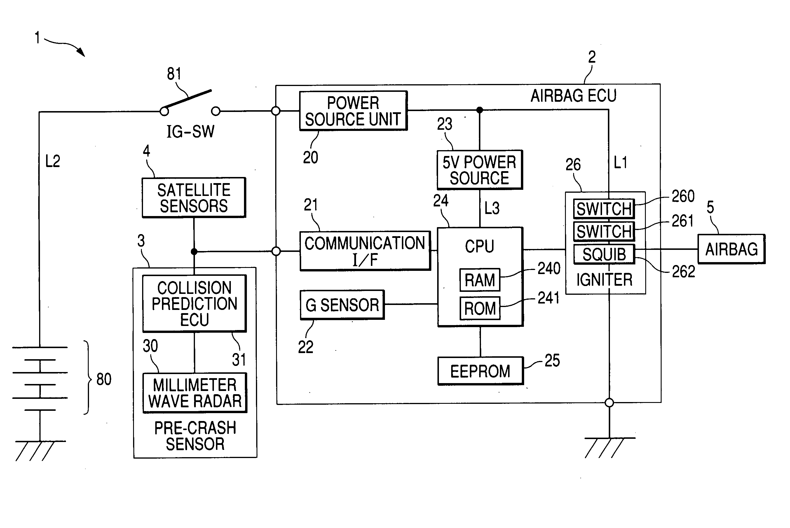
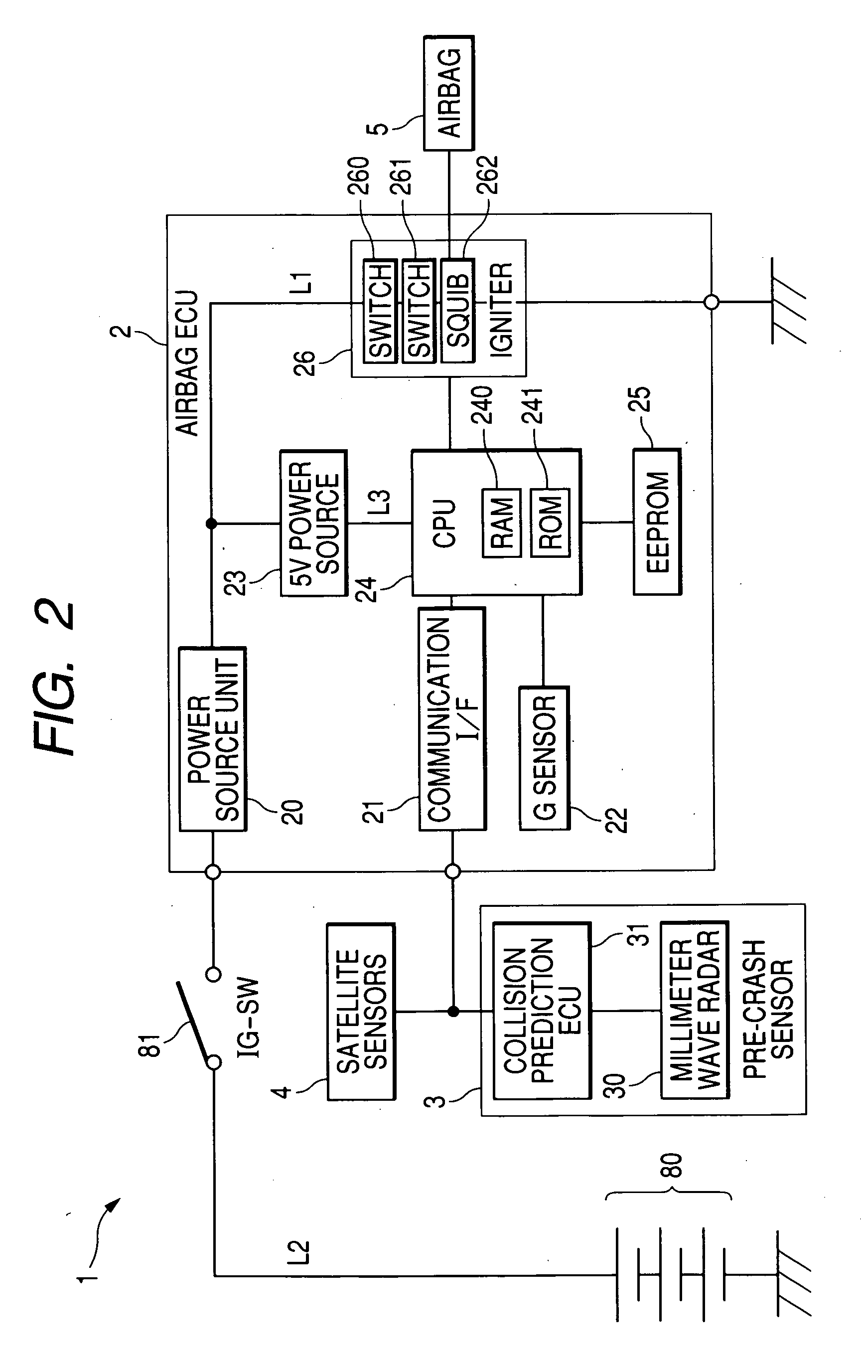
[0039] In this embodiment, an airbag system representing an occupant restraint system is described.

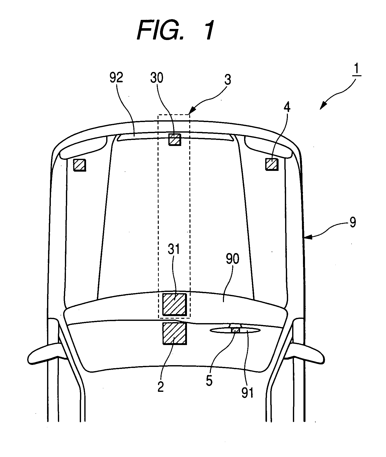
[0040]FIG. 1 is a partial top view showing an arrangement of an airbag system disposed on a vehicle according to the first embodiment. FIG. 2 is a block diagram of the airbag system.

[0041] As shown in FIG. 1, an airbag system 1 of a vehicle 9 has an airbag ECU (or occupant restraint controller) 2, a pre-crash sensor (or collision predictor) 3, a pair of satellite sensors (or acceleration detectors) 4, and an airbag 5. The airbag system 1 represents an occupant restraint system according to the present invention. The airbag ECU 2 denotes an occupant restraint ECU of the occupant restraint system.

[0042] The airbag 5 is embedded in a folded shape into a central area of a steering wheel 91. The airbag 5 denotes an occupant restrainer of the occupant restraint system.

[0043] The pre-crash sensor 3 has a millimeter wave radar 30 and a collision prediction ECU 31. The millimeter wave radar...


PUM


Abstract

An occupant restraint system of a vehicle has an airbag, a pre-crash sensor which calculates a probability of a collision of a vehicle with an object and outputs a pre-crash signal indicating a prediction of the collision when the probability is higher than a predetermined value, a satellite sensor which detects a degree of acceleration of the vehicle and starts outputting an acceleration signal indicating the detected degree of acceleration in response to the pre-crash signal, and an airbag ECU which processes the acceleration signal to obtain a processing result and deploys the airbag when the processing result indicates a collision of the vehicle with the object. Therefore, because the airbag ECU does not start processing the acceleration signal until the satellite sensor outputs the acceleration signal in response to the pre-crash signal, a load on the airbag ECU can be alleviated.

Description

CROSS-REFERENCE TO RELATED APPLICATION [0001] This application is based upon and claims the benefit of priority of the prior Japanese Patent Application 2004-44545 filed on Feb. 20, 2004 so that the contents of which are incorporated herein by reference. BACKGROUND OF THE INVENTION [0002] 1. Field of the Invention [0003] The present invention generally relates to an occupant restraint system in which an occupant restraint device such as an airbag is instantaneously actuated at a vehicle collision time to protect occupants of a vehicle. [0004] 2. Description of Related Art [0005] An airbag system of a vehicle has a satellite sensor, an airbag electronic control unit (ECU) and an airbag(s) (see Published Japanese Patent First Publication No. 2002-67870). The satellite sensor is embedded, for example, in a front-end area or a center pillar of the vehicle. The airbag ECU has a G sensor, a central processing unit (CPU) and an igniter. The airbags are embedded in a folded shape, for examp...

Claims


Application Information

Patent Timeline
Patent Type & Authority Applications(United States)
IPC IPC(8): B60R21/01B60R21/0132B60R21/0134B60R21/16
CPCB60R21/013B60R21/0134B60R21/0132
Inventor KONDO, TOSHIHIDEASO, MAKOTO
Owner DENSO CORP
Why Eureka
Try Eureka