Quick disconnect bipod mount and clamp assembly

a clamp and bipod technology, applied in the field of clamps, can solve the problems of inconvenient and difficult use, bulky, inconvenient and difficult to use, and the ability of the bipod to mount, so as to achieve the effect of convenient use, convenient use, and convenient us

Active Publication Date: 2005-09-01
KENGS FIREARMS SPECIALTY
View PDF10 Cites 98 Cited by
  • Summary
  • Abstract
  • Description
  • Claims
  • Application Information

AI Technical Summary

Benefits of technology

[0017] The resulting attachment of the clamp assembly to the forearm stock provides a quick and easy attachment of the bipod (or some other accessory) to the firearm and enables the clamp assembly to mount securely to the forearm stock of the firearm in a stable, secure selected position. This prevents the clamp assembly, and thus the accessory carried by the clamp (e.g., a bipod), from shifting fore and aft or wobbling during use.

Problems solved by technology

Most shooters are not able to hold a firearm consistently in a set position without wavering, especially after the onset of fatigue resulting from strain on the shooter due to the size and weight of the firearm.
Early bipod and tripod supports typically were somewhat crude strands that generally were bulky, inconvenient and difficult to use and typically were not easily adjustable.
A problem with conventional bipods has been the ability of the bipod to mount to most firearms without requiring the use of special mounting tools and the machining or modification of the firearm stock to accommodate the bipod.
Additionally, most bipods are not designed for quick and easy attachment and release of the bipod from the firearm stock.
However, these bipod mounts do not provide for the quickly releasing an attached bipod support from the firearm.
The problem with the Parker-Hale bipod is that to mount the bipod to a firearm, the forearm stock of the firearm generally must be modified to mount a track or slide therein, along which the mounting block is received to mount the bipod to the firearm.
Such modifications generally are expensive and often must be done by specialty gunsmiths and can mar the finish of the firearm.
Clamping objects to forearm mounted picatinny rails is usually a lengthy, cumbersome process requiring that the shooter juggle small parts in the field.

Method used


Image

  • Quick disconnect bipod mount and clamp assembly
  • Quick disconnect bipod mount and clamp assembly
  • Quick disconnect bipod mount and clamp assembly

Examples


Embodiment Construction

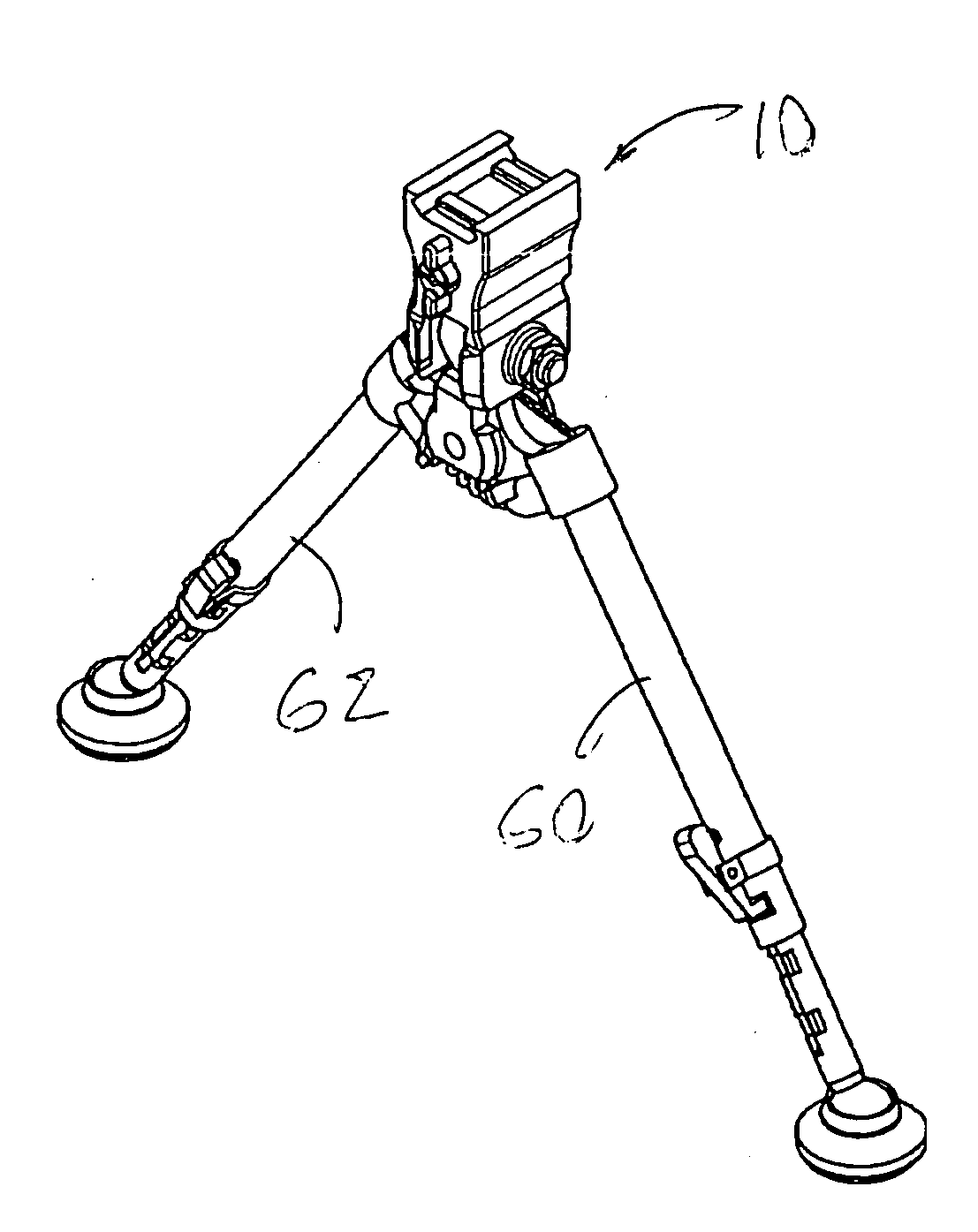
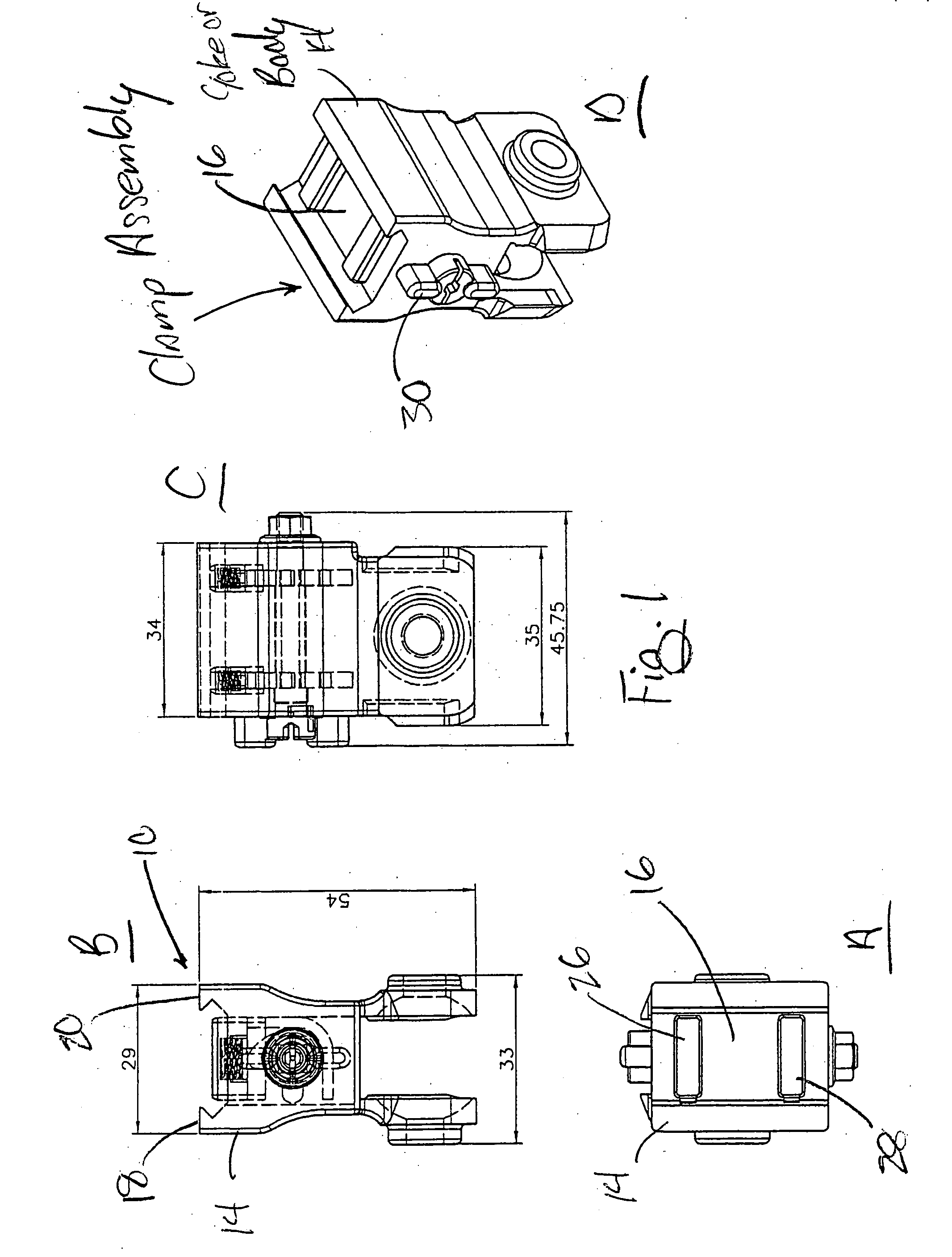
[0029] Referring now to FIGS. 1a-10 in which like numerals indicate like parts throughout the several views, the present invention comprises a clamp assembly 10 for mounting an accessory or support such as a bipod 12 to a firearm or other device or instrument. The clamp assembly 10 is generally is mounted to the forearm stock portion of the firearm via an elongate weaver style or picatinny arsenal style elongate mounting rail 50 as typically affixed below and carried on the front end of a rifle's forearm stock.

[0030] Mounting rail 50 can be any suitably strong and rigid elongate supporting structure but, in the above described illustrative embodiment, is a picatinny rail mounting structure (i.e., a MIL-STD-1913 picatinny rail) having a plurality of evenly spaced standard size transverse grooves (e.g., 50, 54, as best seen in FIG. 10). Mounting rail 50 is preferably aligned in parallel with an instrument's operational axis (e.g., such as the central axis of a firearm's barrel), and ...


PUM


Abstract

A quick disconnect clamping assembly for releaseably attaching an accessory such as a bipod to an elongate support such as a picatinny-style mounting rail comprises a clamp body with a mounting yoke that is adapted to slide over and receive the picatinny rail. The yoke includes a substantially rectangular base plate defining the central upper surface of a clamp body and includes a pair of parallel sidewalls extending upwardly therefrom. The base plate has, in one embodiment, first and second transverse bores for first and second substantially rectangular upwardly movable bolts actuable to project upwardly from the yoke base plate. The clamp body's first and second transverse bolts, when raised and aligned with the transverse grooves of the picatinny rail, are received in the spaced transverse grooves of the rail to attach the yoke to the rail.

Description

RELATED PATENT AND PENDING PATENT APPLICATION INFORMATION [0001] This application claims priority to provisional Patent Application No. 60 / 543,572, filed Feb. 12, 2004, the entire disclosure of which is incorporated herein by reference. This application is owned by the applicant / owner of U.S. Pat. No. 5,711,103 and U.S. Pat. No. 5,815,974, the entire disclosures of which are incorporated herein by reference. Additionally, this application is owned by the applicant / owner of provisional application No. 60 / 338,153, filed Nov. 13, 2001, the entire disclosure of which is also incorporated herein by reference.BACKGROUND OF THE INVENTION [0002] 1. Field of the Invention [0003] The present invention relates to an apparatus and method useful as firearm accessories and support devices such as bipods, and more particularly, relates to a clamp assembly for attaching an accessory to a mounting rail structure affixed to the forearm stock of a firearm. The clamp assembly attaches to the rail struc...

Claims


Application Information

Patent Timeline
Patent Type & Authority Applications(United States)
IPC IPC(8): F41A23/08
CPCF41A23/08
Inventor KENG, DAMATUSZCZAK, MACIEJ W.
Owner KENGS FIREARMS SPECIALTY
Why Eureka
Try Eureka