
Rotary engine

a rotary engine and engine technology, applied in the field of rotary engines, to achieve the effect of increasing efficiency

Inactive Publication Date: 2005-09-01
CHOU JUNG KUANG
View PDF2 Cites 7 Cited by
  • Summary
  • Abstract
  • Description
  • Claims
  • Application Information

AI Technical Summary

Benefits of technology

[0005] The present invention is to provide a rotary engine getting rid of the limitation of a conventional piston engine, which can avoid the defects of the limitation by the low temperature rotation, the intermittent gas intake and discharging to elevate the combustion temperature for increasing efficiency.
[0006] A character of the present invention is to solve the problem of thermal expansion in the engine, wherein it can keep the pressure and friction between the block and the wheel approach to zero in order to reduce the force of resistance and to increase its horsepower. The effect is composed of the block and the point of the support, between which a suitable angle is formed relating to the round wheel, which can be supported by a roller.

Problems solved by technology

According to the principal theory of combustion, the traditional method uses low-density mixture gases, wherein the distance between each oil molecule is far that is difficult for being ignited.

Method used


Image

  • Rotary engine
  • Rotary engine
  • Rotary engine

Examples


Embodiment Construction

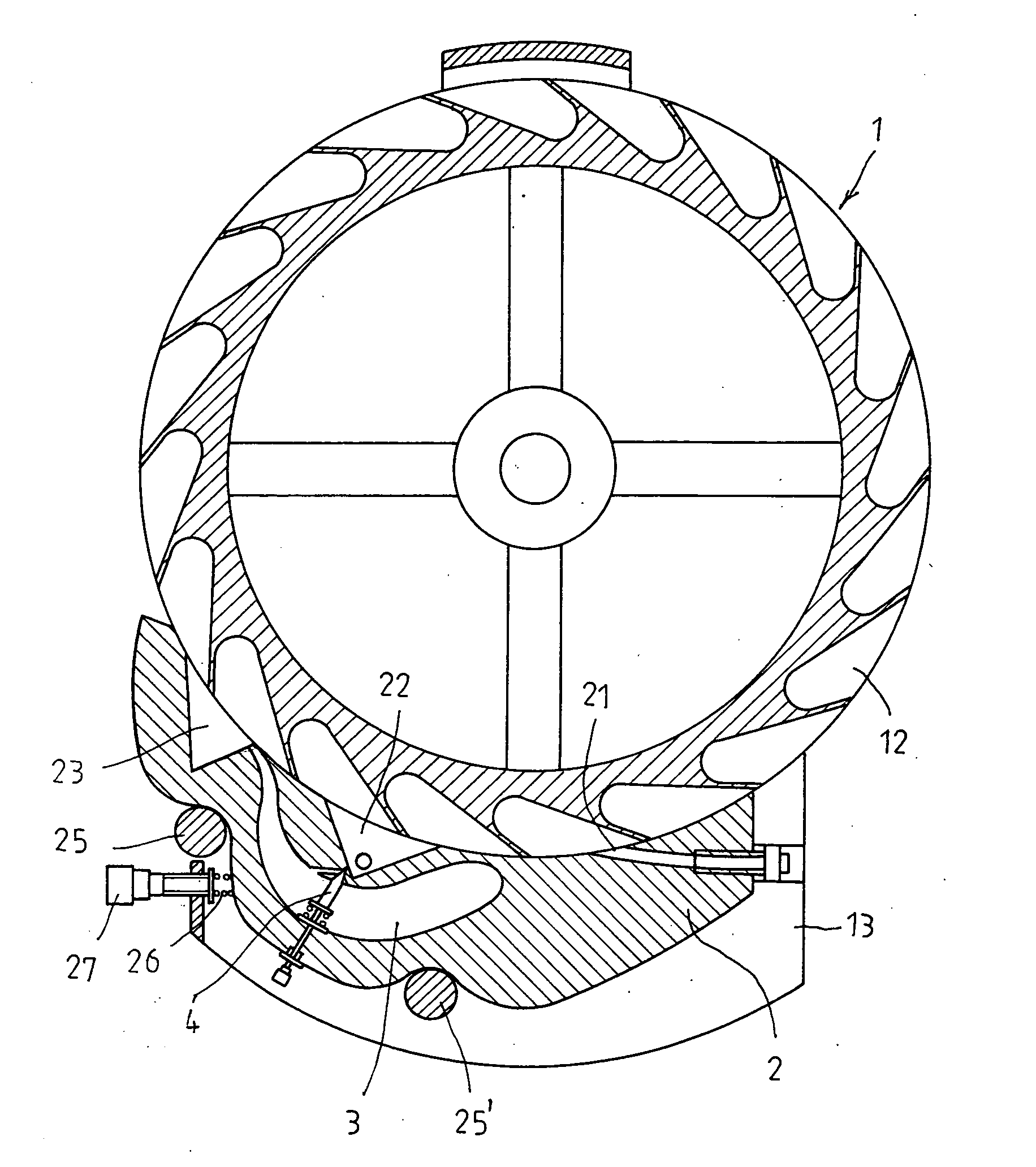
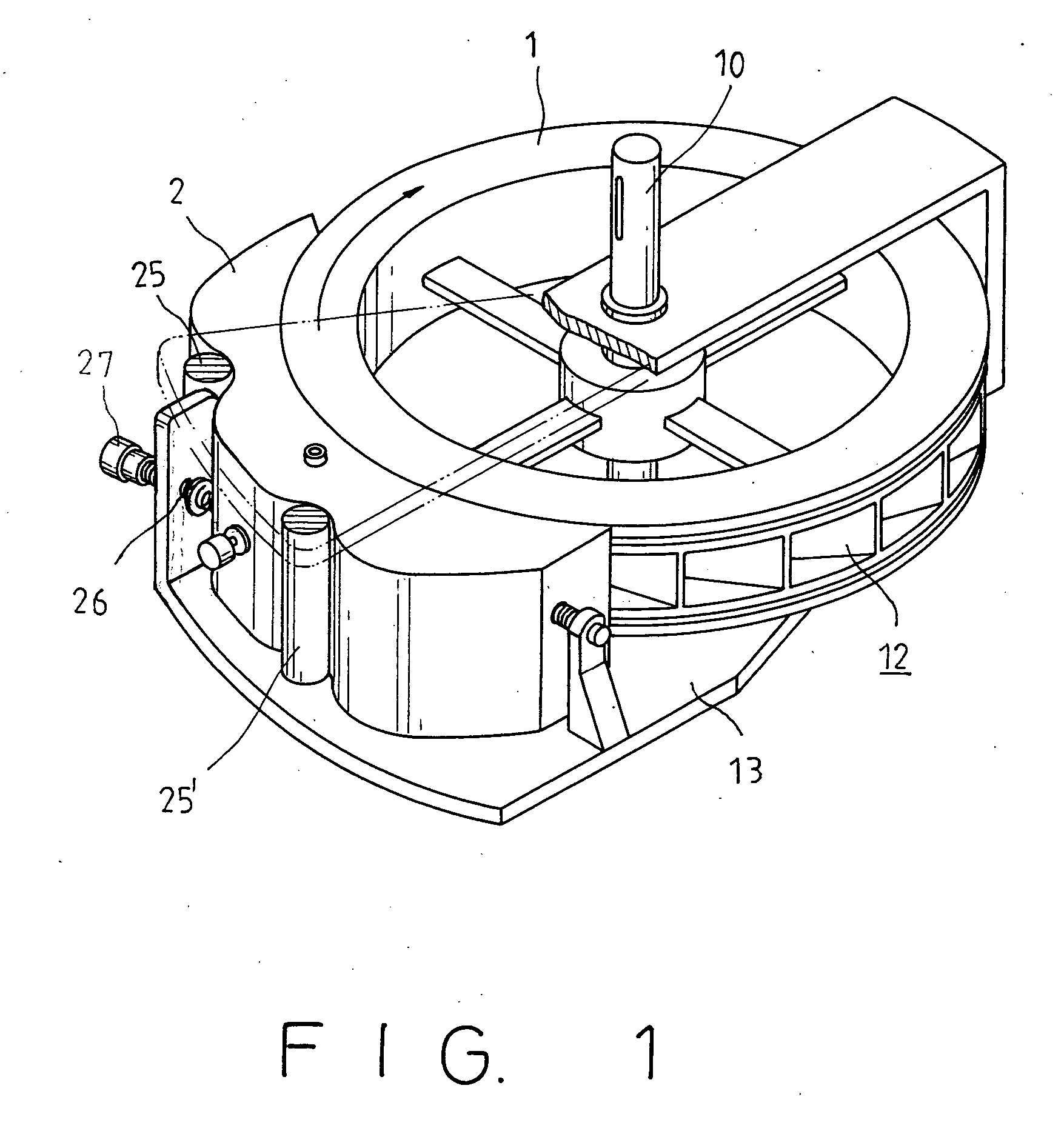
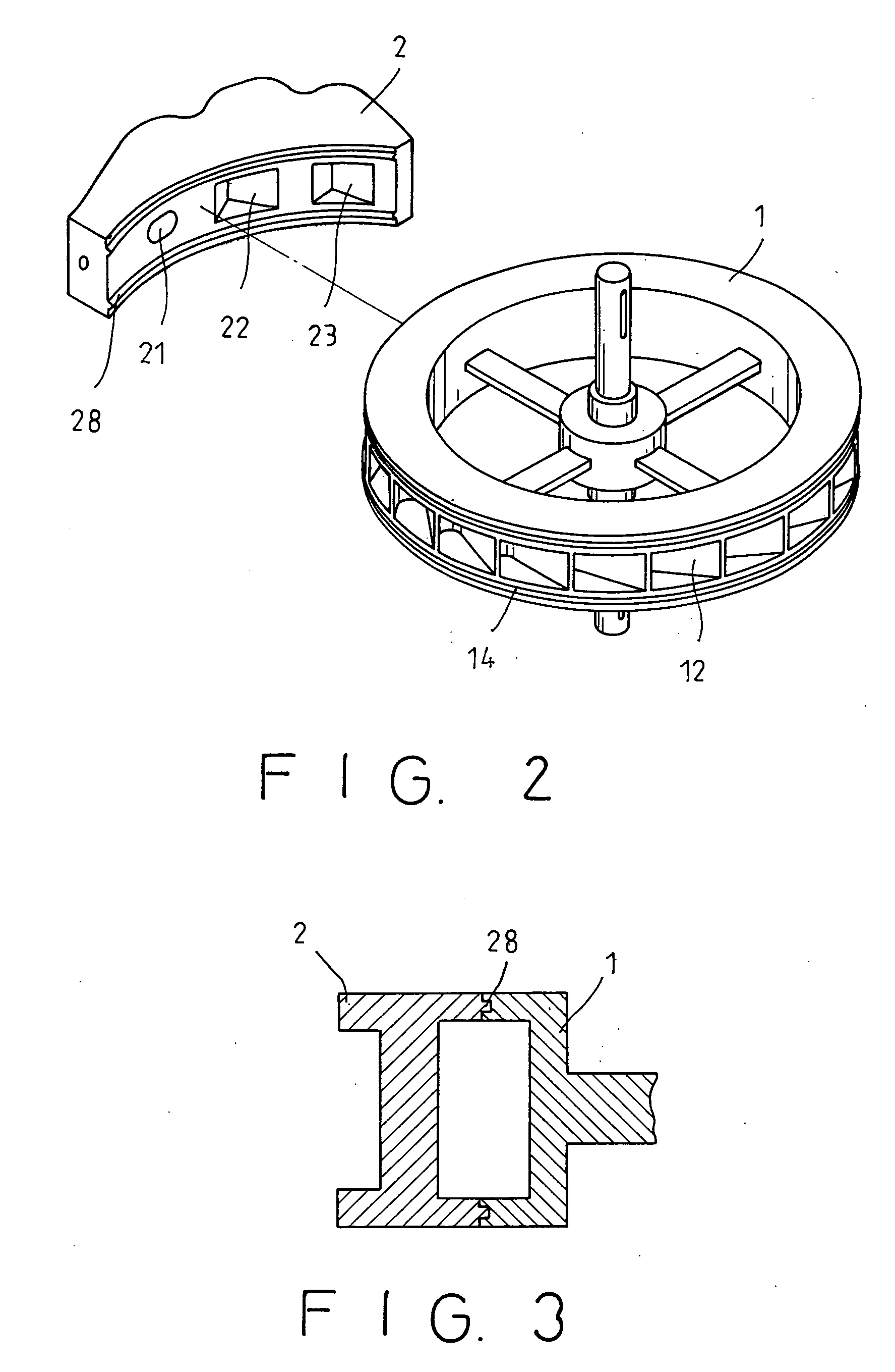
[0017] Please referring to FIG. 1 to 4, the present invention includes a round wheel (1), of which a shaft (10) is pivoted on a frame (13) to provide kinetic force during rotating. The round wheel (1) is provided with a plurality of pockets (12) being capable of any suitable configuration. At least one block (2) is located at a lateral side or round surface of the wheel (1) with a suitable oblique angle to keep stable contact with the round surface of the wheel (1) by use of elastic force provided by a spring (26) mounted on a screw (27) connected on the frame (13), wherein the block (2) is provided with a convex ring (28) for fitting with concave portion (14) formed on the wheel (1), as shown in FIGS. 2 and 3. The block (2) is also provided with an intake aperture (21), a combustion chamber (22), and a power room (23), which are opposite to pockets (12) of the wheel (1) to form quasi cylinders. A cooling room (3) provided in the block (2) has a released valve (4), which communicate...


PUM


Abstract

A rotary engine includes a round wheel, which has a shaft pivoted on a frame to provide kinetic force during rotating, wherein the round wheel is provided with a plurality of pockets. At least one block is located at a lateral side or round surface of the wheel, which keeps stable contact with the round surface of the wheel by use of elastic force provided by a spring mounted on a screw and provides a suitable oblique angle between the block and the wheel. The block has an aperture, a combustion chamber, and a power room, which are opposite to pockets of the wheel to form quasi cylinders. A roller is fixed on the frame to support and maintain the block in stable. Acting force, which can be produced when mixture fuel is input into the pocket, when the fuel is ignited and exploded in the combustion chamber, and when expansion gas is exhausted into the power room, pushes the wheel to rotate continuously for outputting efficient kinetic force for utilization.

Description

[0001] This application is a continuation-in-part of U.S. application Ser. No. 10 / 900,192 filed on 28 Jul. 2004 being a continuation-in-part of U.S. application Ser. No. 10 / 392,859 filed on 21 Mar. 2003, which had claimed priority on Taiwanese application filed on 3 Apr. 2002.FIELD OF THE INVENTION [0002] The present invention relates to a rotary engine, and especially to an invented and novel apparatus having absolute new structure for providing continuous horsepower as an efficient engine. BACKGROUND OF THE INVENTION [0003] There are various kinds of engines for providing kinetic force in different mechanic apparatus. Each engine is designed for a certain purpose in utilizing a related machine with a specific way to supply the horsepower. It is popular that most land vehicles use reciprocating piston engines, which are characterized in that their torques are normal in low rotating speed. The known reciprocating piston engine generally must have a suitable clearance between the pis...

Claims


Application Information

Patent Timeline
IPC IPC(8): F01D1/34F02B53/02F02C5/04
CPCF01D1/34Y02T10/17F02C5/04F02B53/02Y02T10/12
Inventor CHOU, JUNG KUANG
Owner CHOU JUNG KUANG
Learn More