
Unique multiple point initiated shaped charge perforator and method for its use

a technology of initiation and perforation, which is applied in the direction of wellbore/well accessories, lighting and heating equipment, and domestic stoves or ranges, etc. it can solve the problems of increasing the flow of oil and gas through the perforation into the wellbore, and achieves the reduction of mechanical risks, the effect of reducing the potential for bridging, and increasing the effectiveness of treatmen

Inactive Publication Date: 2005-09-01
BAKER ERNEST L +5
View PDF35 Cites 49 Cited by
  • Summary
  • Abstract
  • Description
  • Claims
  • Application Information

AI Technical Summary

Benefits of technology

[0010] The slot-shaped perforations formed utilizing the shaped charge perforators of the invention minimize the potential for bridging during fracturing treatments, thereby increasing the effectiveness of the treatments and decreasing the mechanical risks involved with such treatments. Since the perforators of the invention are non-linear and have a more conventional exterior configuration than linear shaped charges, they can be easily adapted for use with current oilfield perforating equipment thus eliminating the need to retrain personnel in their use. In addition, the fan-shaped jets produced by the inventive perforators may expose more formation surface area and produce less formation damage than the circular jets that are formed by conventional shaped charge perforators. This, in turn, will result in increased flows of oil and gas through the perforations into the wellbore.

Problems solved by technology

This, in turn, will result in increased flows of oil and gas through the perforations into the wellbore.

Method used


Image

  • Unique multiple point initiated shaped charge perforator and method for its use
  • Unique multiple point initiated shaped charge perforator and method for its use
  • Unique multiple point initiated shaped charge perforator and method for its use

Examples


Embodiment Construction

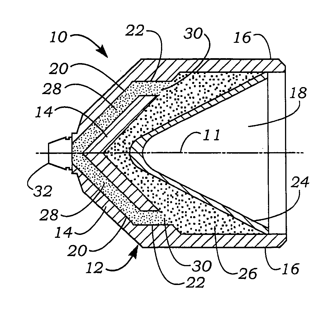
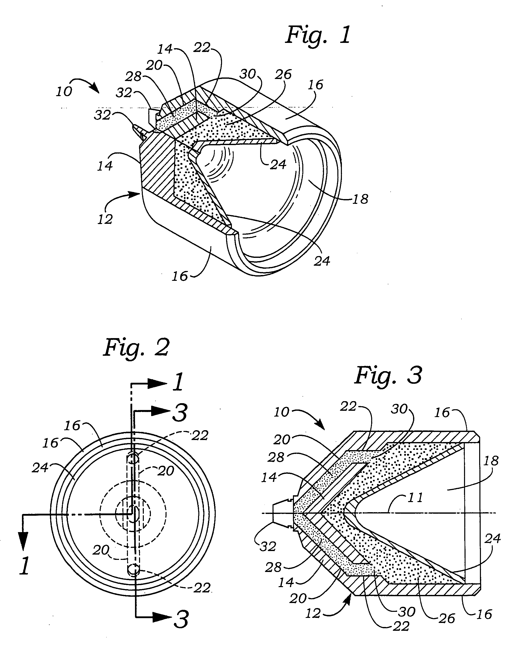
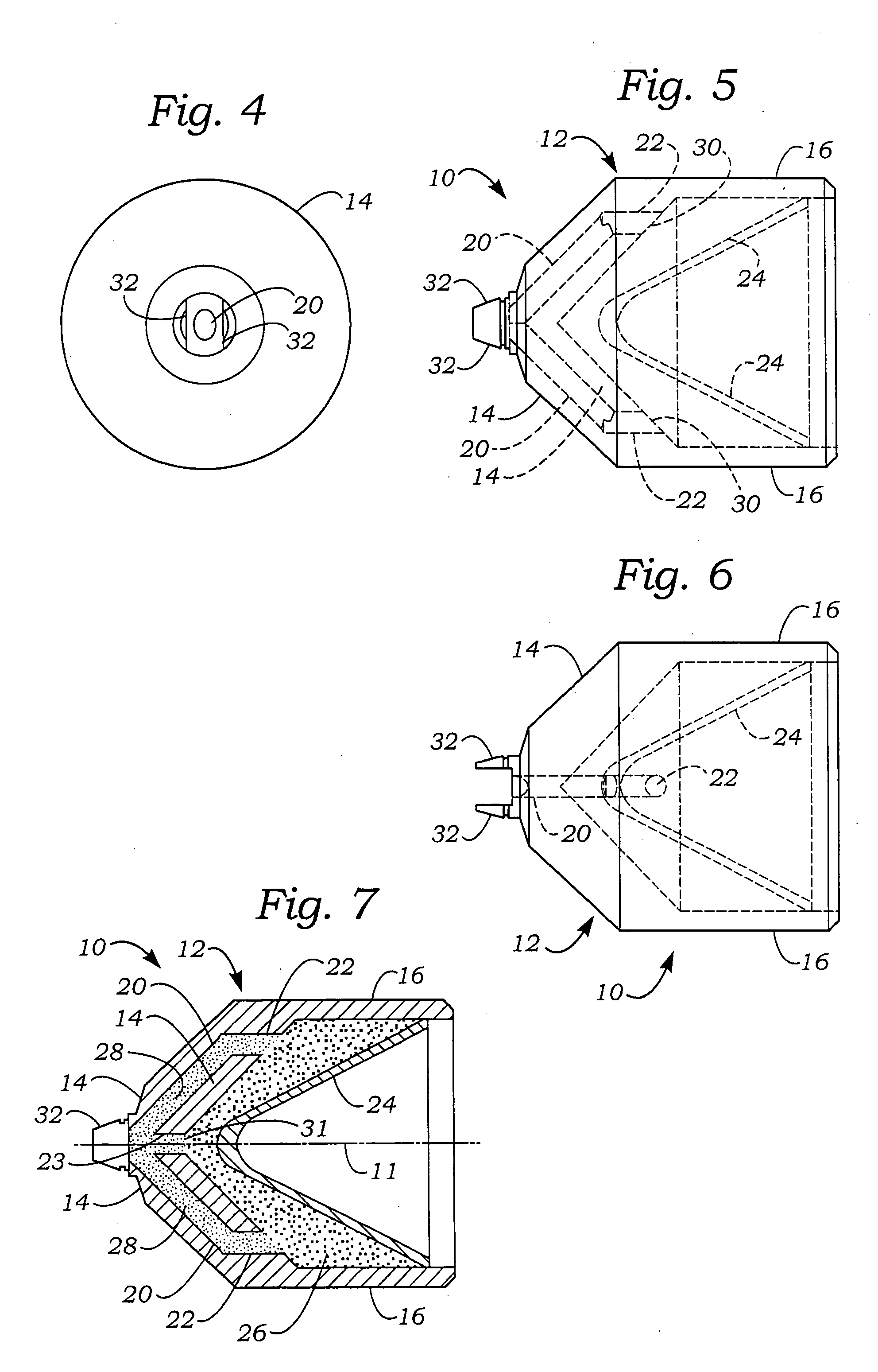
[0022]FIGS. 1-6 in the drawings illustrate one embodiment of the explosive non-linear shaped charge perforator of the invention designated by reference numeral 10. Normally, a plurality of these shaped charges, usually between about 10 and about 1,000 and preferably between about 30 and about 200, are mounted in a helical fashion around the charge tube of a perforating gun, not shown in the drawings, and are conductively coupled together by a detonator cord, which also is not shown in the drawing. The perforating gun is lowered into the casing of a well that has been drilled into a hydrocarbon-bearing formation so that the shaped charge perforators can be detonated to form perforations in the casing, the cement liner between the outside of the casing and the formation, and in the formation itself. The detonator cord is initiated by a blasting cap that is activated by an electrical signal generated at the surface of the well, and the resultant detonation wave initiates the individual...


PUM


Abstract

A non-linear shaped charge perforator for use in perforating an oil and gas formation into which a wellbore has been drilled comprises a monolithic, axisymmetric metal case in which is disposed a main explosive charge between the front of the case, which is closed with a concave metal liner, and the closed back end of the case. The main explosive charge contains multiple initiation points, preferably two initiation points located about 180° apart on the outside surface of the charge, so that when the perforator is detonated the main charge is initiated such that the metal liner is collapsed into a non-circular jet, preferably a fan-shaped jet, that pierces the casing of the wellbore and forms non-circular perforations, preferably slot-shaped perforations, in the surrounding formation.

Description

BACKGROUND OF INVENTION [0001] This invention relates generally to oilfield perforating and fracturing using explosive shaped charges and is particularly concerned with a method of forming non-circular perforations in hydrocarbon-bearing subterranean formations using a uniquely designed shaped charge perforator having multiple initiation points. [0002] After a well has been drilled and casing has been cemented in the well, perforations are created in the casing, cement liner and surrounding formation to provide paths or tunnels in the formation through which oil and gas can flow toward the well, through the holes in the cement liner and casing and into the wellbore for transportation to the surface. These perforations are typically cylindrical or round holes made by conventional explosive shaped charge perforators. Usually, these perforators are tightly arranged in helical patterns around downhole tools called well perforators or perforating guns, which are lowered into the wellbore...

Claims


Application Information

Patent Timeline
Patent Type & Authority Applications(United States)
IPC IPC(8): E21B43/117F24B1/00F42B1/02
CPCF42B1/02E21B43/117
Inventor BAKER, ERNEST L.DANIEL, DAVID C.WESSON, DAVID S.BURBA, JOHN L. IIIDANIELS, ARTHUR S.DAVIS, ROBERT E.
Owner BAKER ERNEST L
Learn More