Embroidering machine

a technology of embroidering machine and thread, which is applied in the direction of embroidering machine, spool-pin assembly, textiles and paper, etc., can solve the problems of cumbersome and wrong color thread routing to the specific needl

Inactive Publication Date: 2005-09-01
AISIN SEIKI KK
View PDF2 Cites 17 Cited by
  • Summary
  • Abstract
  • Description
  • Claims
  • Application Information

AI Technical Summary

Benefits of technology

[0017] A second aspect of the present invention is to provide an embroidering machine whose gist is to modify the structure of the first aspect, wherein the color-recognizing device includes an emitting portion from which a beam of light is emitted to the corresponding thread, a receiving a reflection beam of light as a reelection of the emitted beam of light from the thread, and a light shielding device provided between the emitting portion and the receiving portion for the prevention of an entrance of light into the receiving portion except for the reflection beam of light.

Problems solved by technology

In such a case, at least one of the colored threads routed to a specific needle has to be replaced with another colored threads, which may result in that a wrong colored thread is routed to the specific needle.
The above-mentioned cumbersome can be seen whenever, with a specific embroidering machine having single needle, a different embroidering patterns are produced on a common work-piece or different work-pieces.

Method used


Image

  • Embroidering machine
  • Embroidering machine
  • Embroidering machine

Examples


Embodiment Construction

[0039] Hereinafter, an embodiment of an embroidering machine according to the present invention will be described in great detail with reference to the attached drawings.

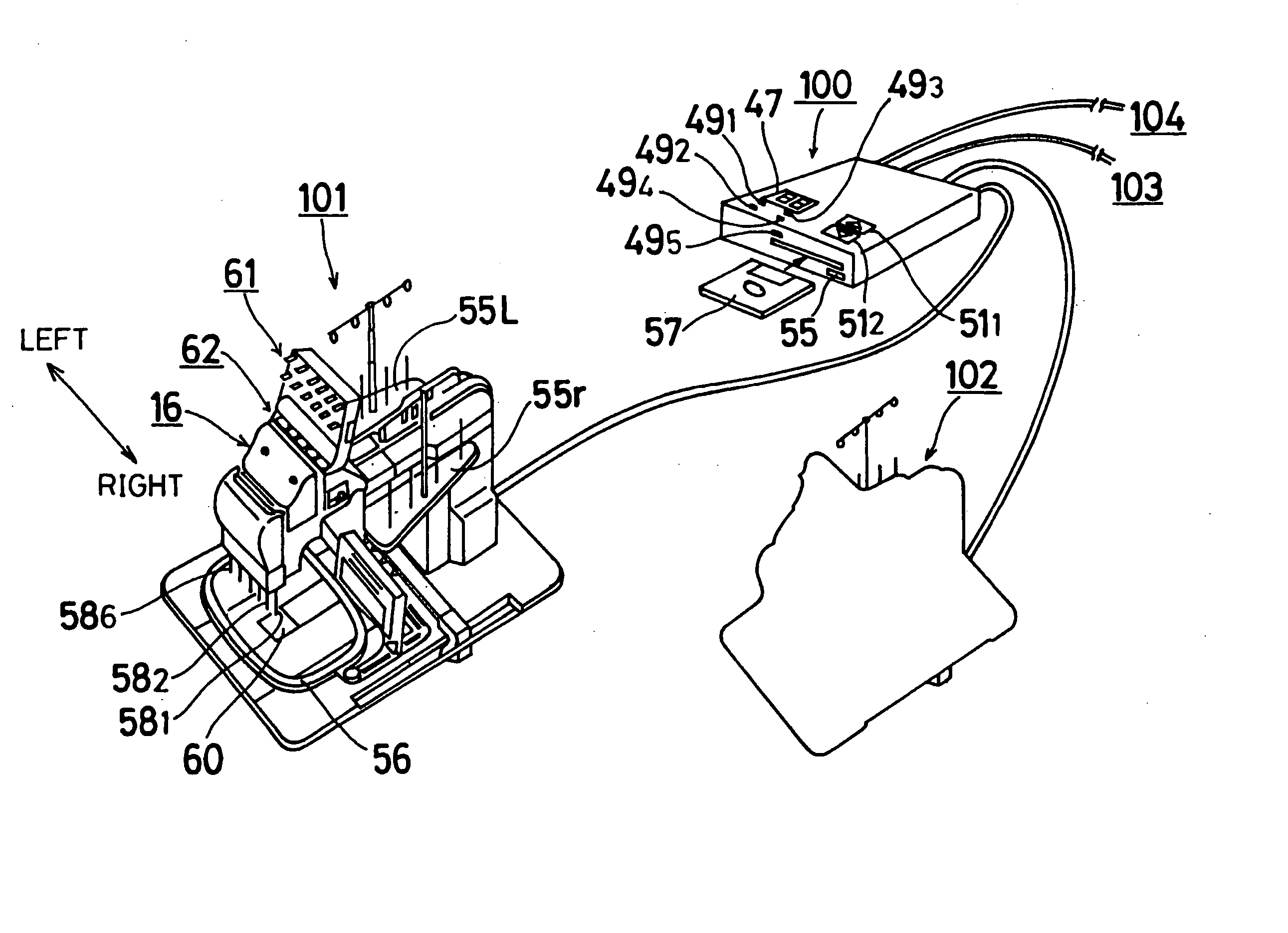
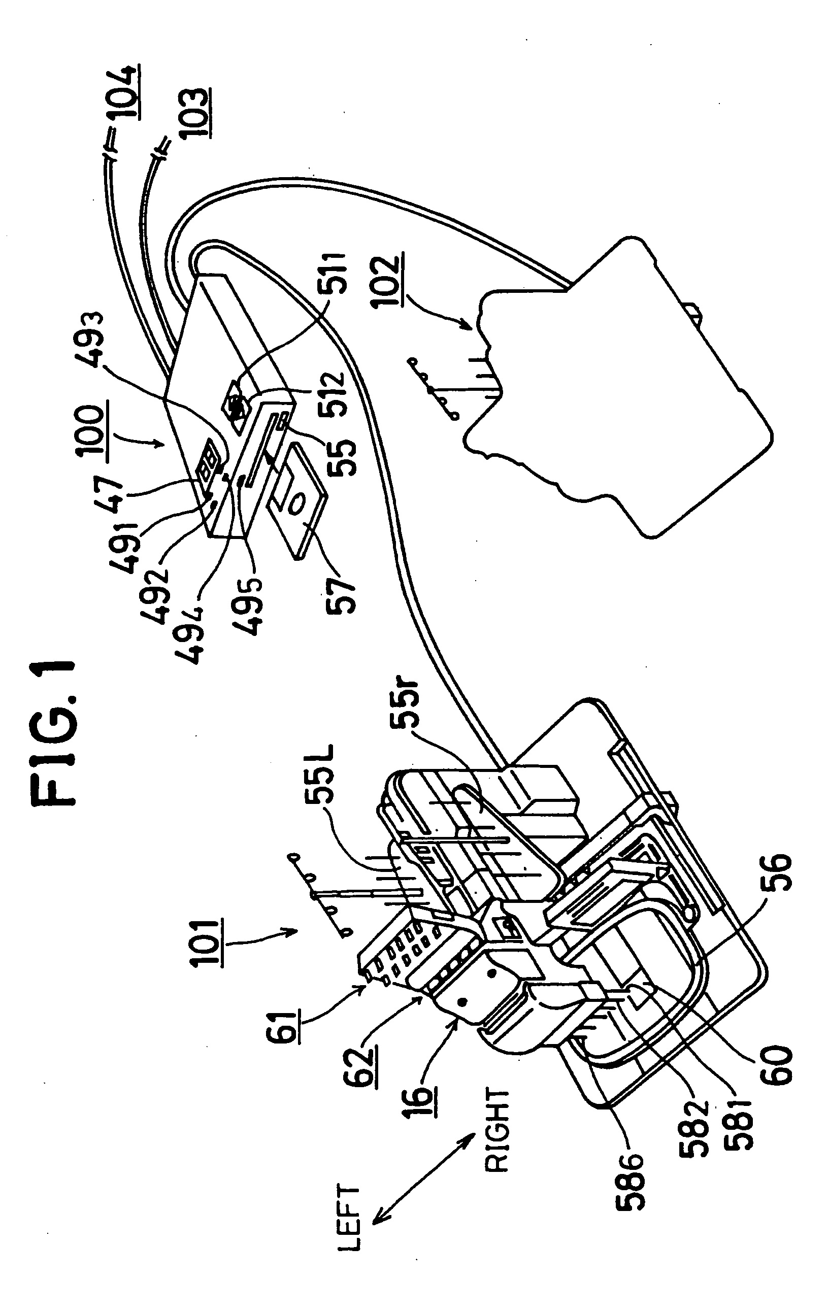
[0040] First of all, with reference to FIG. 1, there is illustrated an embroidering system which includes as maximum as four embroidering machines 101, 102, 103, and 104 each of which is fed with embroidering data from a data transmitting device 100 having a built-in flexible disk device 44. Employing such a flexible disk device 44 makes it possible to establish quick data transfer to the embroidering machines 101, 102, 103, an d 104 after inserting a flexible disk 57 recording therein embroidering data into the device 44.

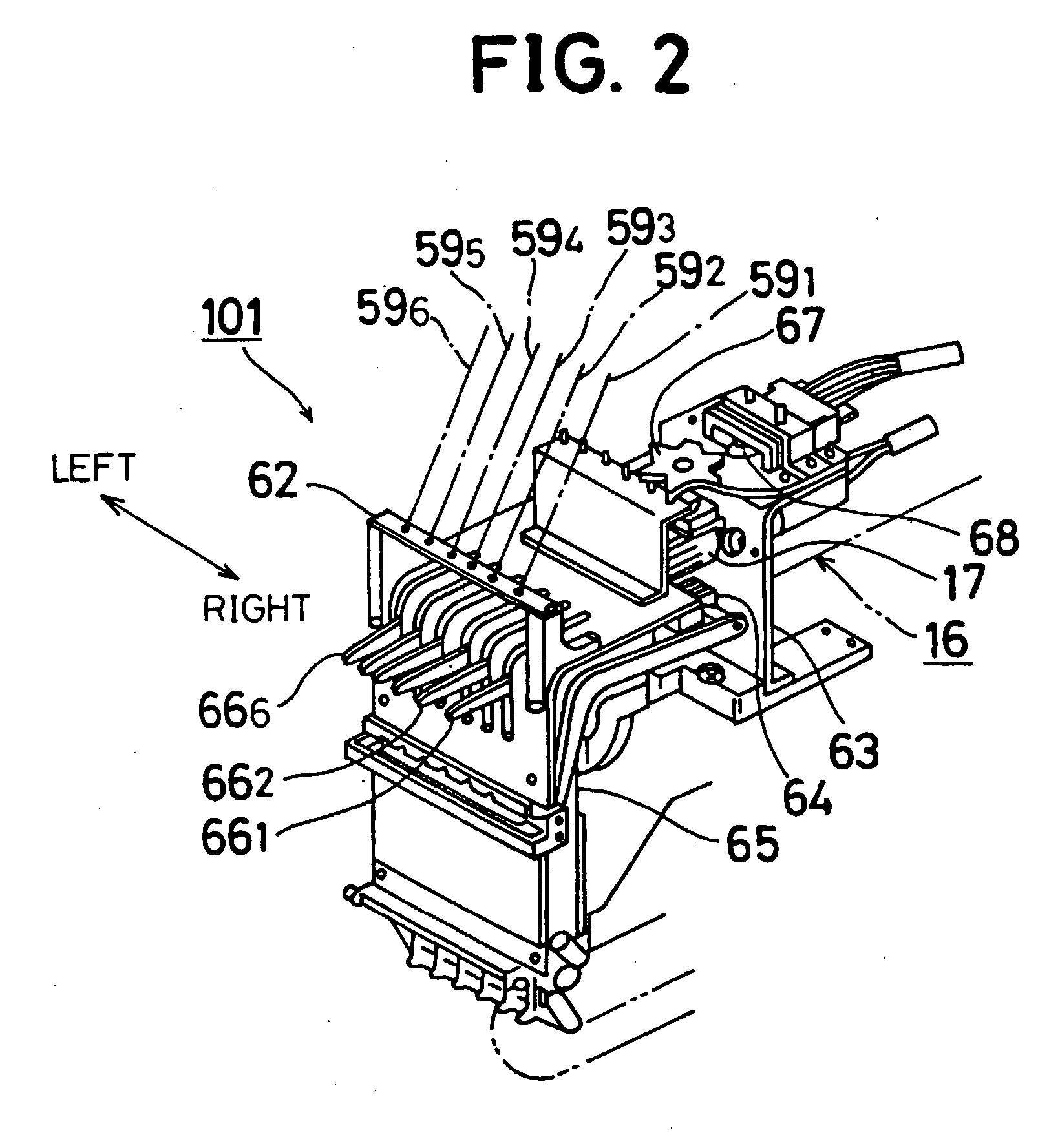
[0041] The four embroidering machines 101, 102, 103, and 104 are identical with each other in construction and operation. The embroidering machine 101, which will be described in extensive detail, includes an embroidering frame driving device 6 which serves for establishing an in-horizontal-plane...


PUM


Abstract

The present invention provides an embroidering machine which is made up of a thread station at which a plurality of spools of different colored threads are installed; a frame on which a work-piece is carried in tension mode; an embroidery stitching mechanism having a plurality of needles to which the colored threads are routed, respectively, and stitching the work-piece with the colored thread routed to a selected needle; a color recognizing device for recognizing the color of each of the threads routed to the respective needles; data reading means for reading embroidering data relating to the embroidering pattern; a comparing device matching a color indication included in the embroidering data with the color of each of the threads which is recognized by the color recognizing device, the comparing device selecting one of the threads to which the thread of the matched color is routed for determining the selected needle; and a control device for controlling the selected needle of the embroidery stitching mechanism and the frame to produce an embroidering pattern on the work-piece with the matched color thread. The color recognizing device includes an emitting portion from which a beam of light is emitted to the corresponding thread, a receiving a reflection beam of light reflected from the thread, and a light shielding device provided between the emitting portion and the receiving portion for the prevention of an entrance of light into the receiving portion except for the reflection beam of light.

Description

[0001] The present application is based on and claims priority under 35 U.S.C § 119 with respect to Japanese Patent Application No. 2004-031034 filed on Feb. 6, 2004 (the 16th Year of Heisei), the entire content of which is incorporated herein by reference. BACKGROUND OF THE INVENTION [0002] 1. Field of the Invention [0003] The present invention is generally directed to an embroidering machine and in particular to an embroidering machine which has a mechanism being capable of establishing automatic change of a thread to another. [0004] 2. Prior Art [0005] One of the conventional embroidering machines of the type is disclosed in, for example, the Publication of Japanese Patent No. 2802395 issued on Jul. 17, 1998 (the 10th year of Heisei). This embroidery machine includes a thread station at which a plurality of thread-wound spools are installed, a selecting mechanism which selects a thread wound on one of the spools, an embroidery stitching mechanism having a plurality of needles for...

Claims


Application Information

Patent Timeline
Patent Type & Authority Applications(United States)
IPC IPC(8): D05B19/12D05B21/00D05B43/00D05C11/16
CPCD05C11/16D05B19/12
Inventor GOTO, HISAHARUFURUICHI, MIKIO
Owner AISIN SEIKI KK
Why Eureka
Try Eureka