
Quick set-up and take-down umbrella system

a quick setup and umbrella technology, applied in the field of umbrellas, can solve the problems of complex shade and support structure of such umbrellas, limited space underneath umbrellas, heavy weight, etc., and achieve the effect of convenient portability and storag

Inactive Publication Date: 2005-09-01
WOLCOTT STEVE
View PDF46 Cites 4 Cited by
  • Summary
  • Abstract
  • Description
  • Claims
  • Application Information

AI Technical Summary

Benefits of technology

[0009] An object of the present invention is to provide a portable and easily-operated umbrella, which is convenient for recreational and vehicle applications. Another object is to provide a quickly-disassembled and quickly-assembled umbrella, which can be set-up and operated without complex instructions, so that the umbrella may be quickly deployed, for example, on a raft or boat.
[0010] The present invention is an umbrella system that comprises a shade portion and a support system, which connect to each other and to a supporting surface preferably in a manner that allows quick-connection and quick-disconnection. The invented umbrella system includes an easily-operated opening and closing system that is accessible underneath the umbrella shade central axis, wherein the user opens and “locks” the shade with one single upwards motion, and “unlocks” and collapses the umbrella in one single downwards motion. The simplicity of construction and operation and the quick-connect features of the umbrella system make it especially beneficial for river rafting and other activities in which the user needs a light weight umbrella and has limited time and limited footing and maneuvering room in which to install and operate an umbrella.
[0013] Light weight, strong materials may be used for the support mast, arm, and fabric shade, and, because there need be no internal workings or parts, except perhaps parts of the quick-connections or a ball joint, the umbrella system may be light-weight and easily portable and storable on a boat, raft, or other vehicle. Preferred embodiments of the invented umbrella system do not require cables, cable-locks, or movement of the support system for operation of the opening / closing mechanism. The preferred retaining system is workable due to the forces caused by the relative positioning of the walls of the umbrella shade, the push-rods, and the slidable hub at the umbrella axis.

Problems solved by technology

In this first category, the space underneath the umbrella is limited, because the support pole takes up space and obstructs movement underneath the umbrella.
The shade and support structure of such umbrellas are typically complex, heavy, and difficult to operate, because the cable extends typically from the lower central axis of the umbrella shade portion, through the umbrella axis, suspension arm and all the way to the lower end of the support pole, and because a crank and lock mechanism is needed to control movement of the cable.
Consequently, these complex umbrellas are not very portable or quickly-operated, so that they are used in situations in which the umbrella is stationary, on a patio or street, and does not need to be moved or frequently opened or closed.
Like the cable-operated umbrellas, these umbrellas are complex, and tend to be heavy and difficult to operate.

Method used


Image

  • Quick set-up and take-down umbrella system
  • Quick set-up and take-down umbrella system
  • Quick set-up and take-down umbrella system

Examples


Embodiment Construction

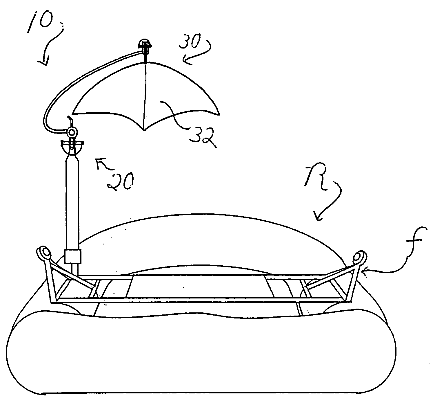
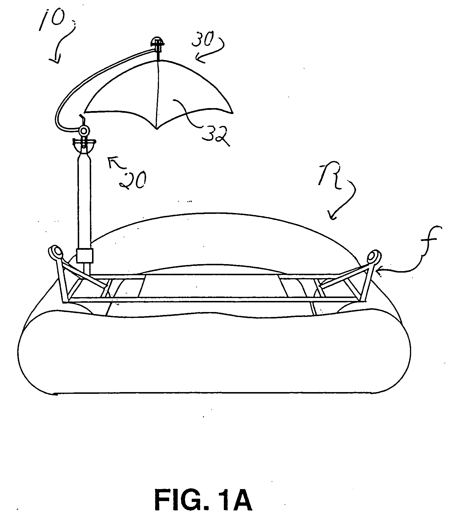
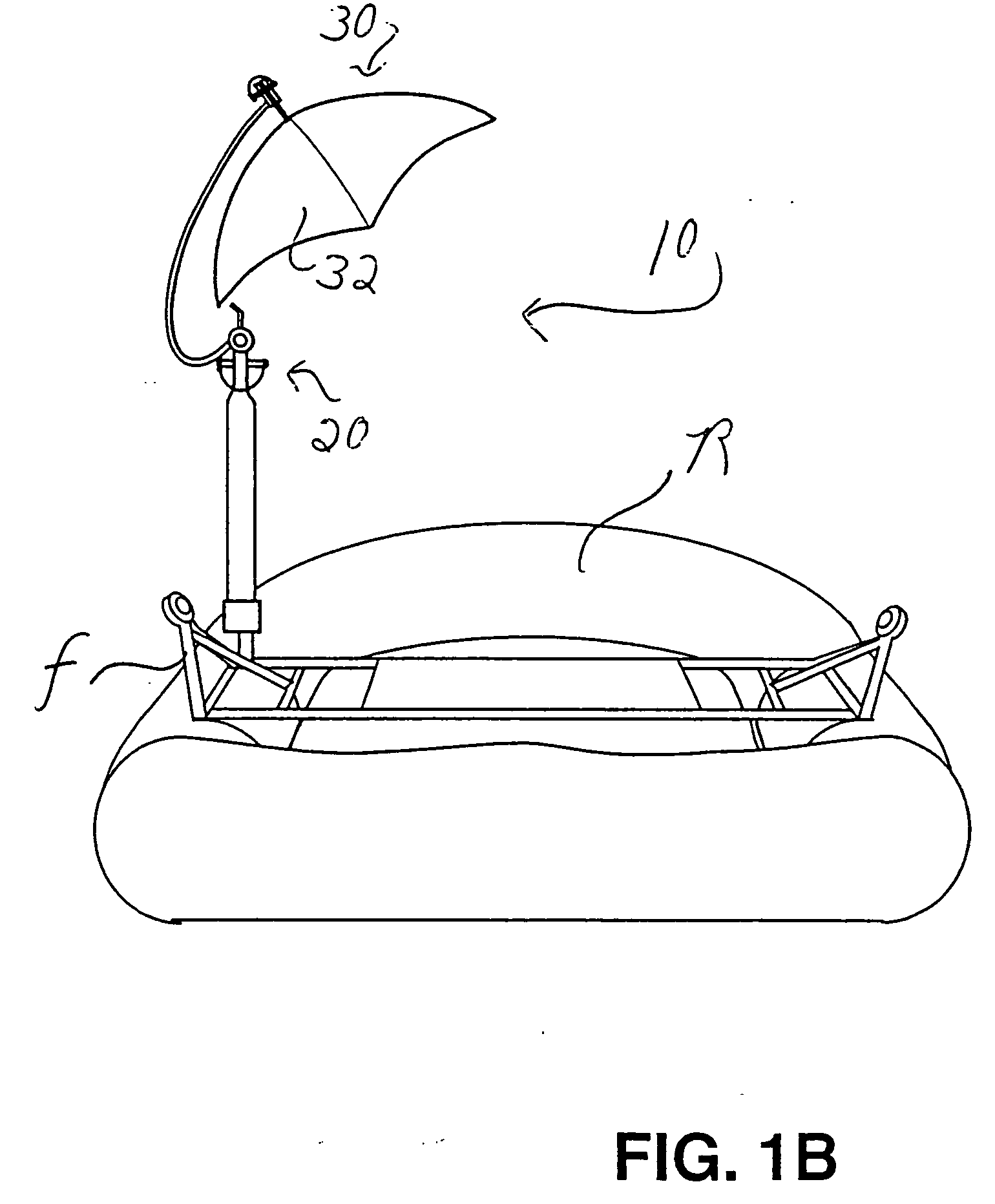
[0024] Referring to the Figures, there are shown several, but not the only, embodiments of the invented umbrella system, and components thereof. FIG. 1A illustrates the preferred embodiment of the umbrella system 10 in use on a river raft “R”, in a generally non-tilted position, wherein the umbrella axis is generally parallel, but offset from, the axis of the mast that attaches to the raft frame “F.”FIG. 1B illustrates the preferred embodiment of the umbrella system on the raft, with a joint adjusted to tilt the umbrella to an alternative position, wherein the umbrella axis is non-parallel to the mast axis. This way, the umbrella shade may be tilted to various positions over the raft, depending on the location of the sun relative to the raft and depending on the position of the people in the raft. FIGS. 2 to 4 illustrate details and operation of the preferred embodiment. FIG. 5-11 illustrate various quick-connections for the multiple connections in the support structure of the umbre...


PUM


Abstract

An umbrella system adapted for easy use on rafts and other moving vehicles is described. The umbrella system hangs from an overhead curved arm, and preferably includes one or more quick-connection / quick-disconnection systems so that the umbrella system can be quickly removed from the raft or vehicle and disassembled into several, shorter, more compact parts. The preferred umbrella opening and closing system does not include cables, cranks, or other complex structure, but rather is made from a handle underneath the center of the umbrella that can be manually pushed and pulled upward and downward, respectively, to open and close the umbrella. The handle pushes a hub unit to operatively engage or receive a shaft extending down from the apex of the umbrella shade so that the hub unit is generally centered before and during the period of maximum force on the hub unit, that is, the hub unit is centered on the shaft well before the push-rods are being forced past a position wherein they are perpendicular to the axis of the umbrella. Preferably, the hub unit has an interior hollow space that receives and slides along the shaft, the hollow space having a constant inner diameter or a plurality of inner diameters, for example. The umbrella system can be adjusted to shade a large area by a few simple adjustments of a preferred pivotal joint, or by quick detachment of the support system from the raft and re-attachment in another location on the raft, for example.

Description

[0001] This application claims priority of patent application Ser. No. 10 / 313,464, filed Dec. 4, 2002, entitled “Quick Set-Up and Take-Down Umbrella System for Recreational Activities”, issued Mar. 1, 2005 as U.S. Pat. No. 6,860,280, which claims priority of provisional patent application, Ser. 60 / 338,283, filed on Dec. 4, 2001, entitled “Quick Set-Up and Take-Down Umbrella System for Recreational Activities”, which are incorporated herein by reference.BACKGROUND OF THE INVENTION [0002] 1. Field of the Invention [0003] This invention relates generally to umbrellas for shading people from the sun or the elements. More specifically, the invention relates to umbrellas that may be used on river rafts and boats, on other vehicles, and in other recreational settings. The invention relates specifically to an umbrella system that can be quickly set-up or taken down, quickly adjusted, and that is light-weight and easily-operated during travel on a raft or other moving equipment. The preferre...

Claims


Application Information

Patent Timeline
Patent Type & Authority Applications(United States)
IPC IPC(8): A45B23/00B63B7/08B63B17/00
CPCA45B11/00A45B23/00A45B2019/004A45B2023/0006A45B2023/0037A45B2023/0081B63B17/00B63B34/565
Inventor WOLCOTT, STEVE
Owner WOLCOTT STEVE
Learn More