

Method for producing light transmitting plate
a technology of light transmitting plate and molded object, which is applied in the field of method for producing light transmitting plate, can solve the problems of inaccurate thickness or dimension, poor appearance of large-sized light transmitting plate with non-uniform thickness obtained in injection molding methods, and insufficient copying of rough pattern from cavity surface to plate (molded object)
- Summary
- Abstract
- Description
- Claims
- Application Information
AI Technical Summary
Benefits of technology
Problems solved by technology
Method used
Image

Examples
example 1
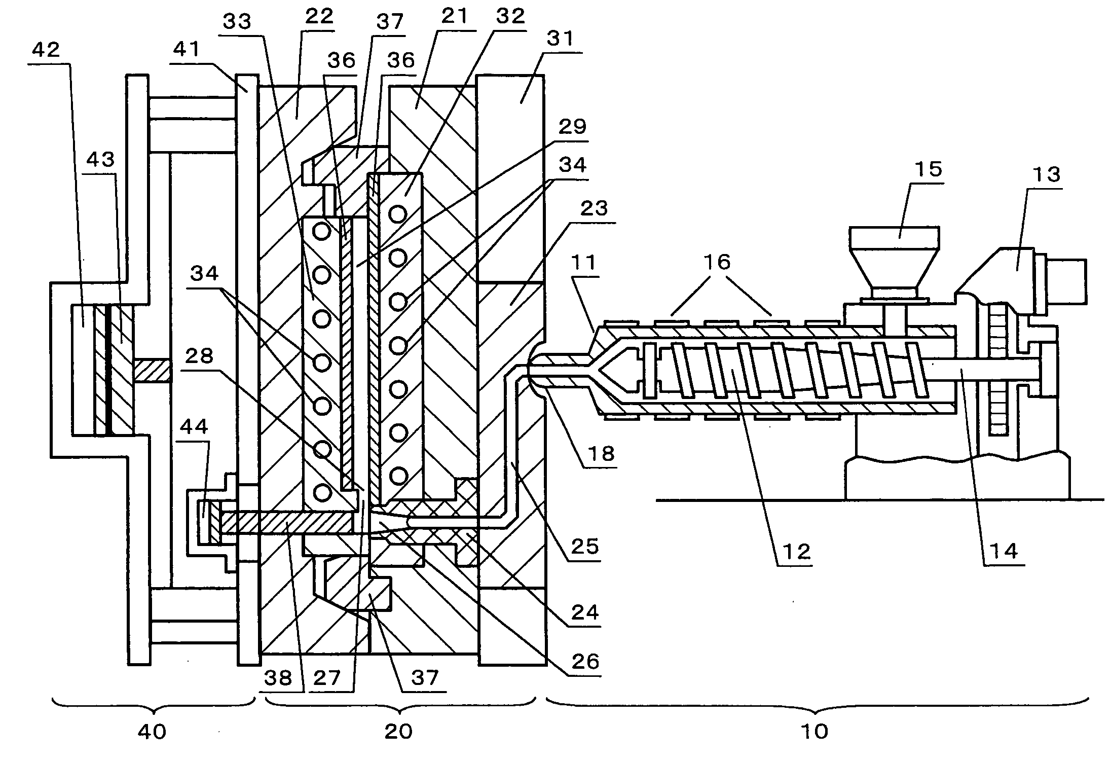
(1) Molding Machine
[0094] A molding machine “J450 EL III”, manufactured by “The Japan Steel Works, Ltd.”, was reconstructed and then was used in Example 1. Using the machine, a molten resin is allowed to flow into a mold continuously by transfer function generated by the screw rotation, while a screw is rotated in a cylinder, to obtain a molded article with a pattern formed on the surface thereof. The machine can mold a resin and form a pattern on the resulting molded article. The machine can be switched to conventional injection molding, with an on-off switch arranged thereon. Therefore, a servomotor of the screw is a torque type that can bear rotational load for a long period of time. Further, the molding machine has a regulating system in which a mold temperature can be monitored at all times by a molding-machine regulating system with a temperature sensor placed in a mold cavity. When a requested set temperature is inputted and the mold temperature reaches the input value, a s...
reference example 1
[0108] Using the same mold as that in Example 1, a light transmitting plate was produced by conventional injection molding, in which a resin was measured and retained in a cylinder of an injection molding device, and then injected. Herein, a mold temperature was kept at 85° C. As a result, a weld line occurred at the center of the product caused by arrangement of two-point gates, and abnormal emission was observed in a final luminance evaluation, whereby the light transmitting plate was determined as defective. Further, copy performance of pattern varies and a large amount of sink occurs, whereby the product was found non-usable as a light transmitting plate. In this case, since a large amount of resin was retained in the cylinder, yellowing of the resin occurs, degrading transparency to result in low final luminance performance.
PUM
| Property | Measurement | Unit |
|---|---|---|
| diagonal length | aaaaa | aaaaa |
| thickness | aaaaa | aaaaa |
| thickness | aaaaa | aaaaa |
Abstract
Description
Claims
Application Information