Clock signal outputting method, clock shaper and electronic equipment using the clock shaper

a clock signal and clock shaper technology, applied in the direction of generating/distributing signals, pulse techniques, instruments, etc., can solve the problems of slave stations that cannot transmit and receive clock signals, slave stations cannot normally receive data from the transmission path, and slave stations cannot reproduce received clock signals, etc., to achieve fast synchronization compensation, quick synchronization compensation, and quick synchronization compensation

Inactive Publication Date: 2005-09-01
SEIKO EPSON CORP
View PDF5 Cites 1 Cited by
  • Summary
  • Abstract
  • Description
  • Claims
  • Application Information

AI Technical Summary

Benefits of technology

[0012] While the clock signal (input signal) based on the signal from the outside is selected, the fixed oscillator does not operate. For this reason, only the clock signal is inputted to a part selecting the clock signal based on the signal from the outside and the alternative clock signal outputted from the fixed oscillator. This eliminates phase noise from being generated by input of the clock signal and the alternative clock signal, thereby obtaining a high quality signal. In addition, when any missing occurs of the clock signal, the fixed oscillator can be operated (oscillated) to switch to the alternative clock signal outputted from the fixed oscillator.
[0014] The clock signal (input signal) based on a signal from the outside and the alternative clock signal outputted from the fixed oscillator can be inputted into the selecting part. While the selecting part is selecting the input signal, the fixed oscillator does not operate (oscillate). For this reason, while the selecting part is selecting the input signal, only the input signal is inputted into the selecting part, therefore, no phase noise occurs in the signal outputted from the selecting part. This allows the clock signal outputted from the selecting part to be of high quality. In addition, if any error such as missing of the input signal, the fixed oscillator can be operated (oscillated) to input the alternative clock signal into the selecting part, and this alternative clock signal can be outputted from the selecting part.
[0015] Furthermore, the clock shaper comprises a phase comparing part receiving inputs of the clock signal or the alternative clock signal outputted from the selecting part and a clock signal from a feedback loop, comparing the phases, and outputting the compared result as a phase difference signal, a loop filter receiving input of the phase difference signal to smooth, and outputting as a control voltage, and a voltage control type oscillating circuit receiving input of the control voltage and outputting a clock signal having a frequency according to the control voltage to the feedback loop and outside. This allows a signal phase synchronized with the input signal or the alternative clock signal inputted into the selecting part to be outputted, thereby resulting in securing quick system synchronization.
[0018] This allows the clock signal to be switched to the standby clock signal when the received clock signal is missing, and thereby the system can be quickly synchronization compensated. Further, the second selecting part and the received clock signal missing detecting part are provided on a pre-stage of the selecting part, and therefore, the system can be quickly synchronization compensated by the alternative clock signal outputted from the fixed oscillator even when the standby clock signal is missing. Further, even when either one of the received clock signal or the standby clock signal is inputted to the selecting part as an input signal, no phase difference occurs in the clock signal outputted from the selecting part.
[0019] In addition, electronic equipment using a clock shaper according to the present invention comprises the above-mentioned clock shaper. This allows electronic equipment capable of quickly synchronization compensating to be obtained even when an external device delays detection of an error such as signal loss (missing) or delays switching operation.

Problems solved by technology

Incidentally, when a line fault occurs in the network, a slave station cannot normally receive data from the transmission path, and cannot reproduce the received clock signal.
In this case, the slave station cannot transmit and receive until the line fault recovers.
As such, there is a problem in that phase noise is generated in the signal outputted from the selecting part when the frequency of the input signal differs from that of the clock signal outputted from the fixed oscillator.
In other words, when the control signal is not inputted into the fixed oscillator, the fixed oscillator does not operate to generate the alternative clock signal.

Method used


Image

  • Clock signal outputting method, clock shaper and electronic equipment using the clock shaper
  • Clock signal outputting method, clock shaper and electronic equipment using the clock shaper
  • Clock signal outputting method, clock shaper and electronic equipment using the clock shaper

Examples


Embodiment Construction

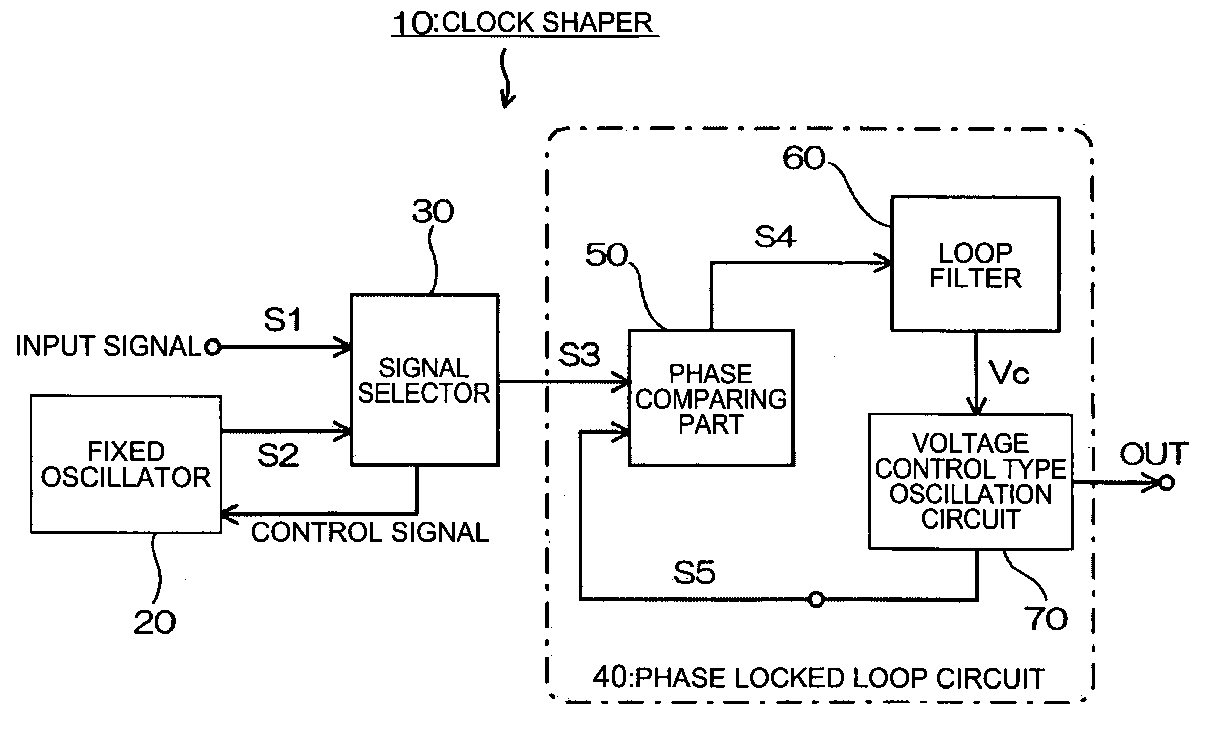
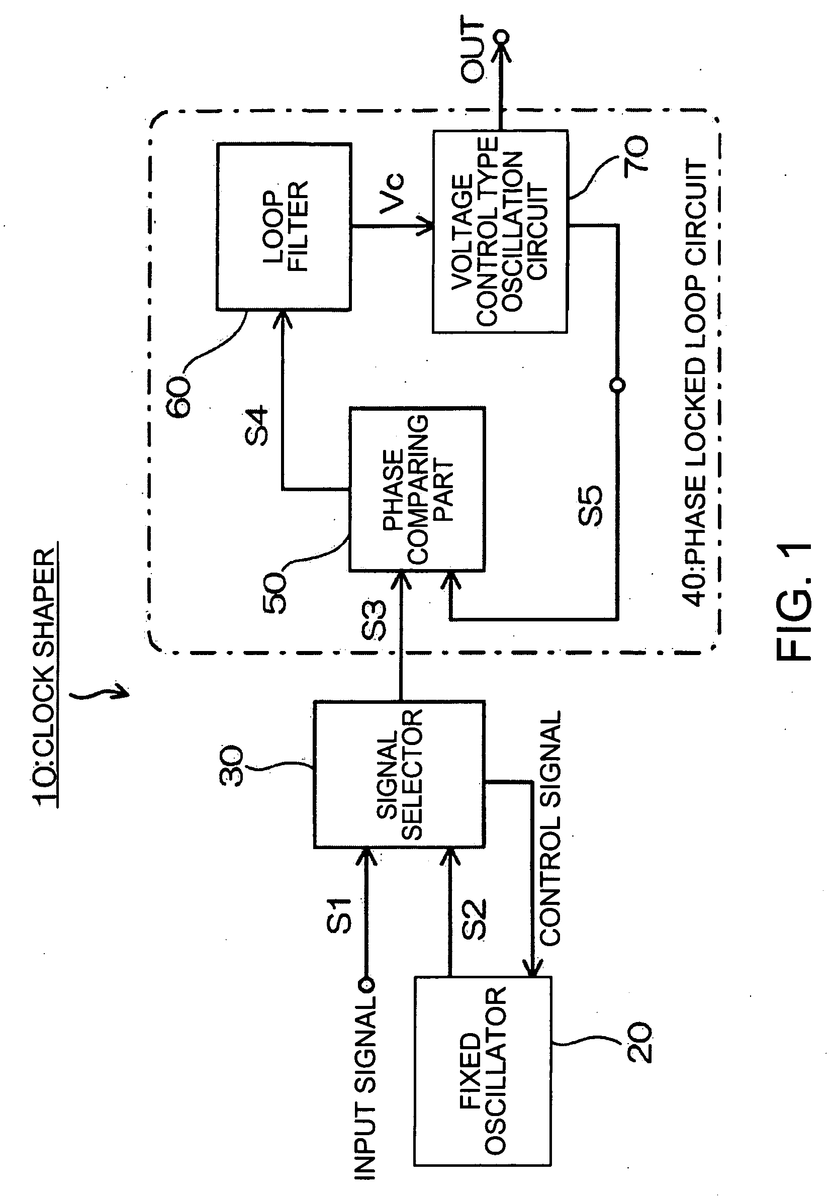
[0026] Preferred embodiments of a clock signal outputting method, a clock shaper and electronic equipment using the clock shaper according to the present invention will be described below. FIG. 1 shows a block diagram of a clock shaper. A clock shaper 10 is constituted to have a signal selector 30, which receives inputs of a clock signal (input signal S1) based on a signal from the outside and an alternative clock signal S2 outputted from a fixed oscillator 20. A Phase Locked Loop (PLL) circuit 40 is connected to a post-stage of this signal selector 30.

[0027] Here, the clock signal based on the signal from the outside is a received clock signal or a standby clock signal, and the received signal refers to a clock signal timing-extracted from data received from a transmission path, and the standby clock signal refers to a clock signal supplied from an external clock supply device (not shown), synchronized with a reference clock signal of a master station or a quasi-master station.

[0...


PUM


Abstract

A clock signal outputting method in which either a clock signal based on a signal from the outside or an alternative clock signal from a fixed oscillator is selected and outputted, wherein, when the clock signal is selected to be outputted, the fixed oscillator is put into non-operating state, and when any error occurs in the clock signal, the fixed oscillator is operated to output the alternative clock signal.

Description

RELATED APPLICATIONS [0001] This application claims priority to Japanese Patent Application No. 2004-056183 filed Mar. 1, 2004 which is hereby expressly incorporated by reference herein in its entirety. BACKGROUND [0002] 1. Technical Field [0003] The present invention relates to a clock signal outputting method, a clock shaper and electronic equipment using the clock shaper, and more particularly relates to a clock signal outputting method, a clock shaper and electronic equipment using the clock shaper specifying the operation of a fixed oscillator provided in the clock shaper. [0004] 2. Related Art [0005] A network clock signal distributes a common frequency into the network and synchronizes the network. A reference clock signal is distributed to each slave station from a master station or quasi-master station of the network. Transmission and reception are performed in each slave station based on a received clock signal timing-extracted from data received from the transmission path...

Claims


Application Information

Patent Timeline
Patent Type & Authority Applications(United States)
IPC IPC(8): H03L7/00H03L7/099H03L7/08
CPCH03L7/0995
Inventor OGISO, HIROYUKI
Owner SEIKO EPSON CORP
Why Eureka
Try Eureka