Flat flexible circuitry

a flexible circuit and signal transmission technology, applied in the direction of flat/ribbon cables, waveguides, high-frequency circuit adaptations, etc., can solve the problem of limited degree of freedom in overall adjustment of ffc, and achieve the degree of freedom of tuning the characteristic impedance of the signal line, improve the electromagnetic shielding effect, and increase the degree of design freedom

Inactive Publication Date: 2005-09-01
NODA ATSUHITO +2
View PDF2 Cites 26 Cited by
  • Summary
  • Abstract
  • Description
  • Claims
  • Application Information

AI Technical Summary

Benefits of technology

[0014] The two-layer lamination of irregular net-like conductive sheets, or layers effectively increases the degree of freedom of designing the signal line with respect of line pattern and line width, changing its space shape, space size and crossing areas. The degree of freedom of tuning the characteristic impedance of the signal line is also increased. The sandwiching shielding structure improves the electromagnetic shielding effect, compared with a FFC length that has a single electromagnetic shielding layer.
[0015] In signal transmission lines of the present invention, the insulative substrate has, on either end, its signal and ground contact pads arranged in parallel on one surface and the dummy and ground pads arranged in parallel on the other surface. The pads on one surface confront those on the other surface on opposite sides of the substrate, and the contact portions of the connector terminal contact and abut the contact pads of the FFC. This arrangement effectively assures that the terminal contacts may be applied to the contact pads at same pressure. Thus, a reliable connection can be made.

Problems solved by technology

Also disadvantageously, the adjustment to the characteristic impedance is limited to only one net layer, and accordingly the degree of freedom in adjustment of the FFC overall is limited.

Method used


Image

  • Flat flexible circuitry
  • Flat flexible circuitry
  • Flat flexible circuitry

Examples


Embodiment Construction

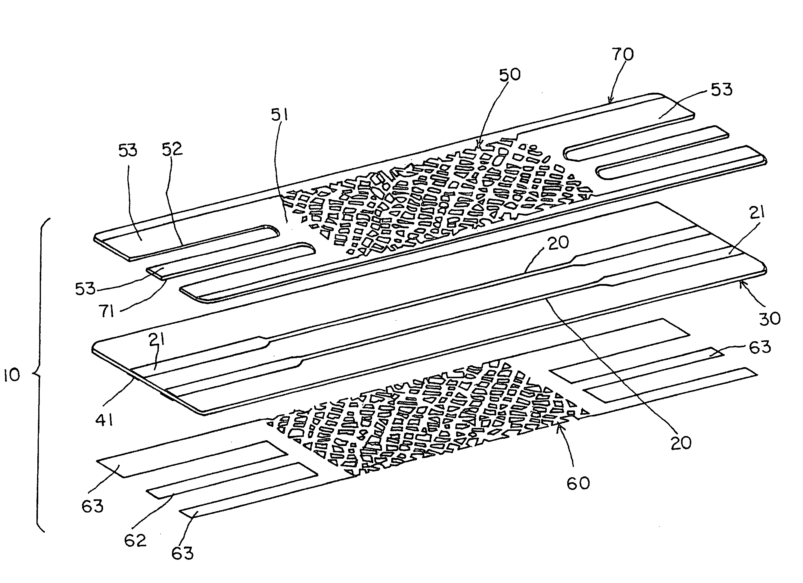
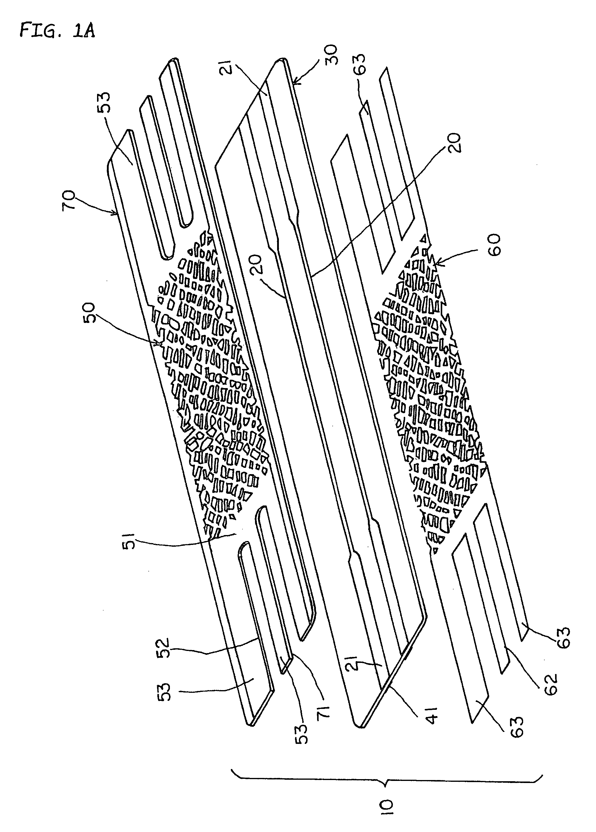
[0027]FIG. 1A shows a signal transmission line in the form of an extent of flat, flexible cable (“FFC”) 10 according to one embodiment of the present invention in the state of being exploded. As shown, on one surface of a flexible insulative substrate 30 extend two signal lines 20 from one to the other end, which signal lines 20 end with signal contact pads 21 at each end of the substrate 30. Dummy contact pads 41 are arranged on the other surface of the substrate 30 and are aligned with (on in onfronting relationship with) the overlying signal contact pads 21 on the one surface of the substrate 30. Two grounding contact pads 63 are arranged on each end of the substrate 30 and are arranged in parallel widthwise along the substrate. The dummy pad 41 is the same as the grounding contact pad 63 in shape and thickness. The dummy pads 41 on the opposite ends of the substrate are not interconnected lengthwise along the substrate, although this is not shown in FIG. 1A.

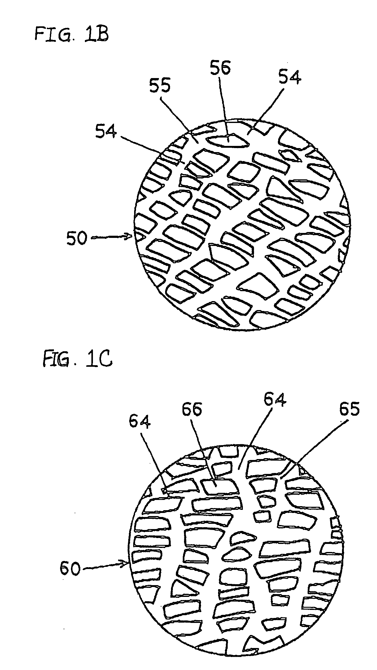
[0028] Net-like cond...


PUM

PropertyMeasurementUnit
conductiveaaaaaaaaaa
sizeaaaaaaaaaa
shapeaaaaaaaaaa

Abstract

An improved signal transmission line whose degree of freedom in designing its signal line pattern and line width and in adjusting its characteristic impedance is significantly increased. The transmission line. The signal transmission line includes an insulating substrate whose one surface has at least one signal line longitudinally extending from one to the other end of the insulating substrate; and two net-like conductive layers laid on the opposite surfaces of the insulating substrate, the spaces for each of the net-like conductive layers being formed at random.

Description

BACKGROUND OF THE INVENTION [0001] The present invention relates generally to a flat signal transmission board taking the form of flat flexible circuitry whose signal lines are shielded, and connectors for making a connection between the same and an associated connector. [0002] One example of conventional signal transmission means is a flat, flexible circuitry (“FFC”) having signal lines disposed on one surface thereof, and a metal sheet on the other surface for shielding the signal lines. In order to improve the flexibility of the FFC, a metal net is used in place of the metal sheet. [0003] In order to permit adjusting of the impedance of the signal lines at high frequencies, the use of a metal mesh whose spaces are irregular in shape and size is shown in Japanese Patent Laid-Open Publication No. 10-112224. According to Japanese Patent No. 3397707, the high-frequency impedance of a length of FFC can be adjusted if its signal lines are sandwiched between upper and lower shield plate...

Claims


Application Information

Patent Timeline
Patent Type & Authority Applications(United States)
IPC IPC(8): H01B7/08H01P3/08H05K1/00H05K1/02H05K1/11
CPCH01P3/08H05K1/0219H05K1/0224H05K1/0253H05K2201/09681H05K1/117H05K1/118H05K2201/0715H05K1/0393
Inventor NODA, ATSUHITOSUZUKI, TERUHITONIITSU, TOSHIHIRO
Owner NODA ATSUHITO
Why Eureka
Try Eureka