Map display device and method for operating thereof

Inactive Publication Date: 2005-09-01
DENSO CORP
View PDF6 Cites 11 Cited by
  • Summary
  • Abstract
  • Description
  • Claims
  • Application Information

AI Technical Summary

Benefits of technology

[0011] The constituent elements can be easily discerned when a group of display colors having high color contrasts is used for coloring the constituent elements of the map display in comparison to when the group of display colors having low color contrasts is used for coloring the constituent elements of the map display. Further, when the group of display colors having high color contrasts is used for coloring the constituent elements of the map display, the user who sees the map display feels less fatigue in his eyes than when the group of display colors of low color contrasts is used for coloring the constituent elements of the map display.
[0014] Further, in the coloring for the particular constituent element of the second color pallet, the intensity of a minor component constituting the color system of the coloring is decreased among the three prime colors of light as compared to the coloring for the particular constituent element of the first color pallet.
[0017] Therefore, the map display device displays the map using display colors of the first color pallet when the vehicle is traveling at low speeds. This approach causes less fatigue to the eyes than the display colors of the second collar pallet. The map is displayed by using display colors of the second color pallet having high color contrasts when the vehicle is traveling at high speeds, thereby enabling the user to quickly discriminate the constituent elements on the map, and shorten the necessary time for seeing the map.
[0019] Therefore, the map display device displays the map using the display colors of the first color pallet which cause less fatigue to the eyes than the display colors of the second collar pallet when the amount of sunlight is smaller than the predetermined value. When the amount of sunlight is greater than the predetermined amount, the map is displayed by using the display colors of the second color pallet having high color contrasts, enabling the user to see the map more vividly.
[0024] Therefore, the coloring of the plurality of the constituent elements from the coloring of the particular constituent element becomes farther with the second pallet than with the first pallet. This makes it possible to vary the color contrast with the particular constituent element as a reference. Here, “farther” means that the distance is large between the colors.
[0027] It is, therefore, made possible to flexibly vary the second color pallet in a manner to increase the color contrast among the constituent elements that are superposed depending upon the superposed state in the display of the constituent elements.

Problems solved by technology

Specifically, according to the above technology, small roads are displayed in the same color as the background color when traveling at high speeds, so that the small roads cannot be substantially seen by a user.
According to this technology, however, the data which cannot be substantially seen may, in practice, be what the user actually desires to confirm.
Therefore, it is not desirable for the display data to be substantially erased even when the two color pallets are switched in displaying the map.

Method used


Image

  • Map display device and method for operating thereof
  • Map display device and method for operating thereof
  • Map display device and method for operating thereof

Examples


first embodiment

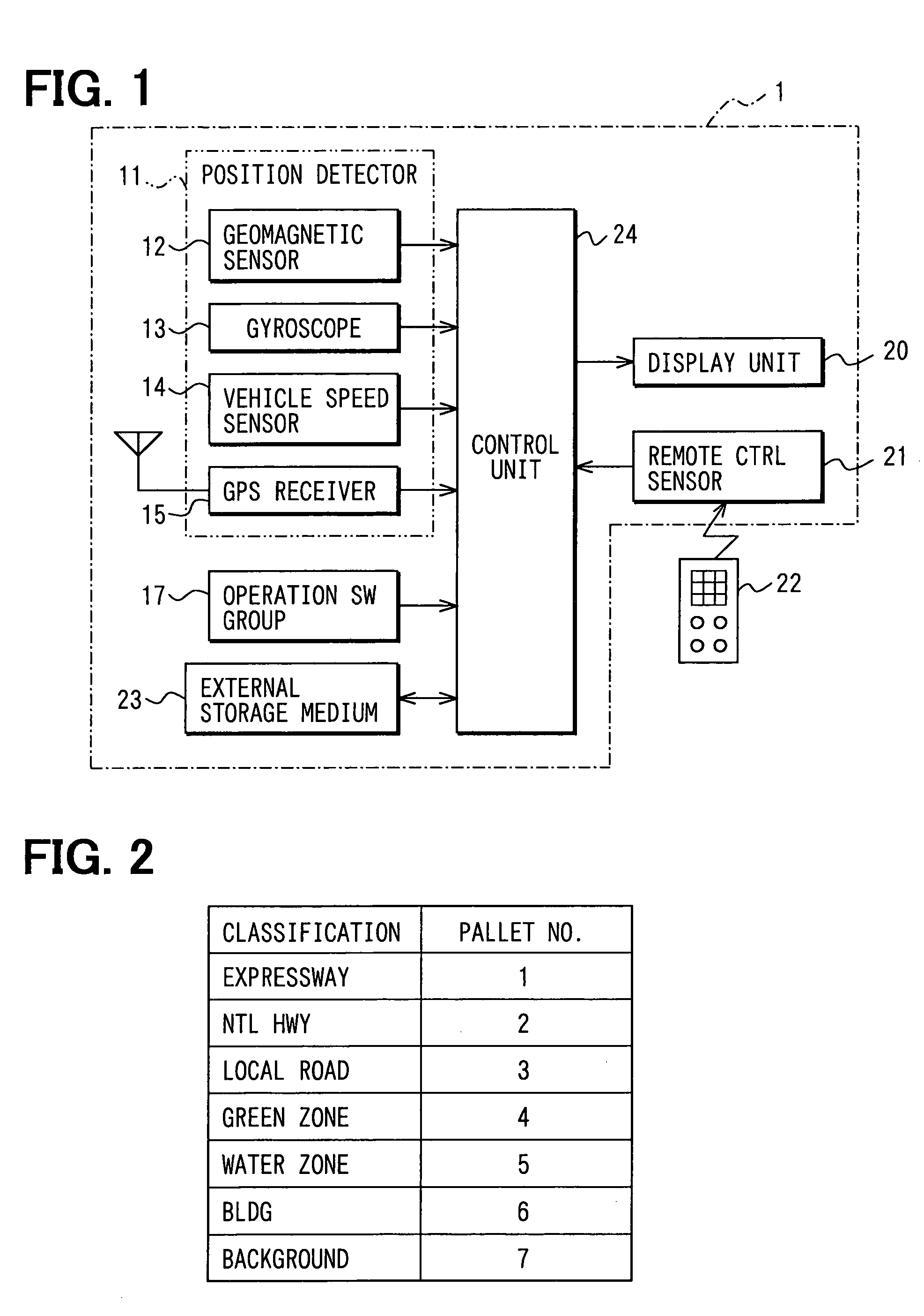
[0040] A first embodiment will now be described. FIG. 1 illustrates a block diagram of a car navigation device 1 according to the first embodiment. The car navigation device 1 includes a position detector 11, an operation switch group 17, a display unit 20, a remote control sensor 21, an external storage medium 23 and a control circuit 24.

[0041] The position detector 11 includes a geomagnetic sensor 12, a gyroscope 13, a vehicle speed sensor 14 for producing vehicle speed pulse signals based on the revolution of a wheel, and a GPS receiver 15 for the global positioning system (GPS) for detecting the position of the vehicle based on the electromagnetic waves from a satellite, all of which are known. These sensors 12 to 15 send, to the control circuit 24, the data for specifying the present position based on various properties.

[0042] The group of operation switches 17 comprises input devices, such as a plurality of mechanical switches provided surrounding the display surface of the ...

second embodiment

[0081] Next, described below is a second embodiment. As for the constitution and operation of this embodiment, described below are only those portions that are different from those of the first embodiment.

[0082]FIG. 8 illustrates the constitution of the car navigation device 1 according to this embodiment. The car navigation device 1 of the second embodiment differs from that of the first embodiment by including a sunlight sensor 25.

[0083] The sunlight sensor 25 is installed near the windshield of the vehicle, and converts light energy of sunlight into electric energy to be output, thereby sending a signal that varies depending upon the amount of sunlight to the control circuit 24.

[0084] In this embodiment, the programs executed by the control circuit 24 are equivalent to the programs executed by the control circuit 24 in the first embodiment except the map display program.

[0085]FIG. 9 is a flowchart of the map display program in the control circuit 24 that receives the signal f...

third embodiment

[0090] Next, described below is a third embodiment of the invention. As for the constitution and operation of this embodiment, described below are only those portions that are different from those of the first embodiment.

[0091] The hardware constitution of the car navigation device 1 of this embodiment is the same as the hardware constitution of the car navigation device 1 of the first embodiment. In this embodiment, the programs executed by the control circuit 24 are equivalent to the programs executed by the control circuit 24 in the first embodiment except the map display program.

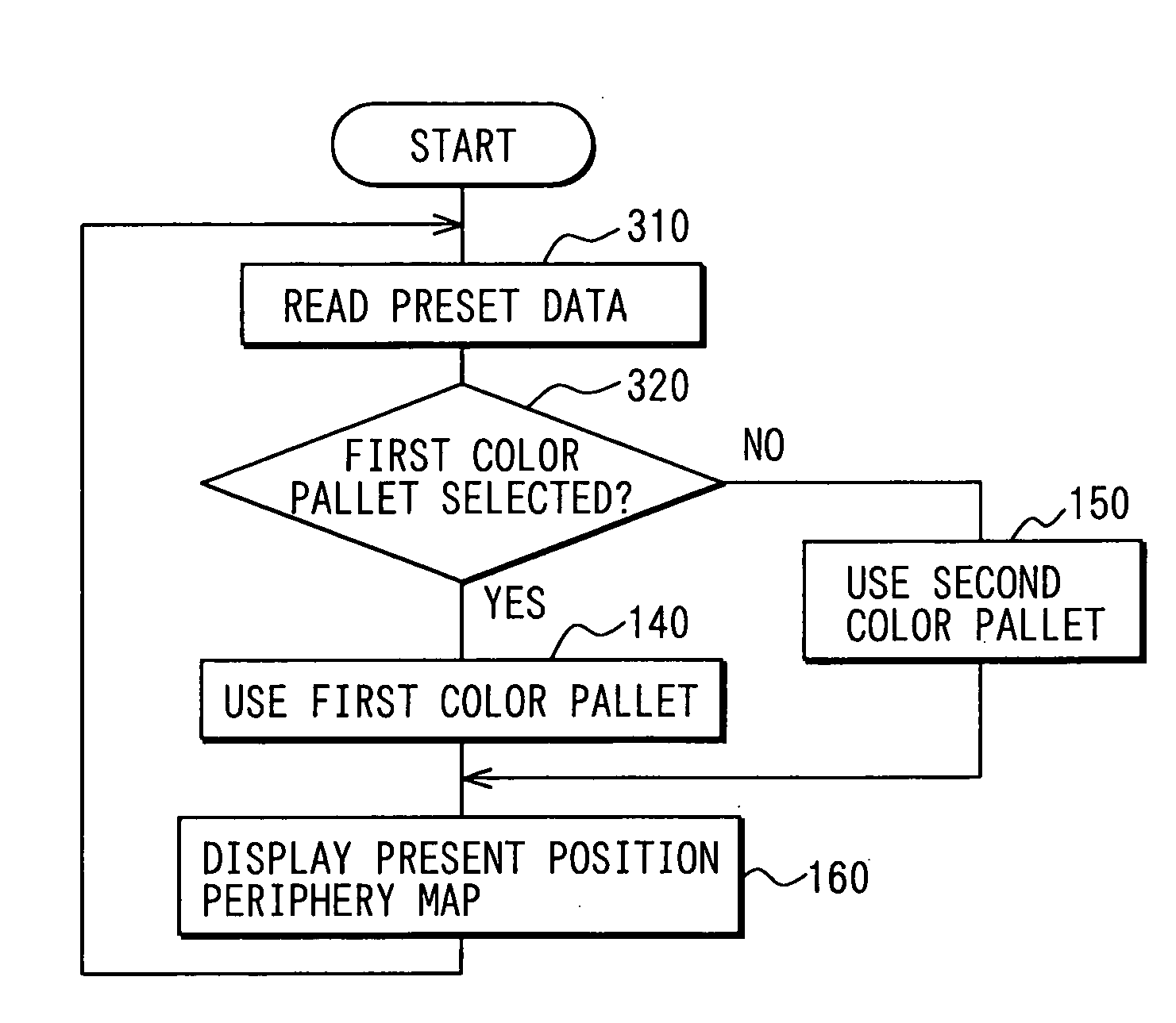
[0092]FIG. 10 is a flowchart of the map display program according to this embodiment. In FIGS. 10 and 5, steps denoted by the same reference numerals executing the same processing are not described here in detail again.

[0093] At step 310, first, preset data is obtained. The preset data refers to data stored in a predetermined region in the external storage medium 23 and include a value for using the f...


PUM


Abstract

A car navigation device displays a map by using display colors included in a first color pallet when the speed of a vehicle traveling is lower than a predetermined value and displays the map by using display colors included in a second color pallet having a group of display colors of contrasts higher than those of the group of display colors of the first color pallet when the speed of the vehicle traveling is greater than the predetermined value.

Description

CROSS REFERENCE TO RELATED APPLICATIONS [0001] This application is based upon, claims the benefit of priority of, and incorporates by reference the contents of, Japanese Patent Application No. 2004-51431 filed on Feb. 26, 2004 and Japanese Patent Application No. 2004-348597 filed on Dec. 1, 2004. FIELD OF THE INVENTION [0002] The present invention relates generally to a map display device of a car navigation device and, more particularly, to a map display device that uses coloring to specify certain elements. BACKGROUND OF THE INVENTION [0003] Conventionally, a display map in a car navigation device uses a color pallet for assigning display colors to constituent elements of the map display such as a road, a landmark and a name of a wide area. The color pallet is data for coloring so that the constituent elements correspond to displayed colors of the constituent elements. [0004] For example, JP-A-3-7638 discloses a car navigation device which includes two kinds of color pallets, and ...

Claims


Application Information

Patent Timeline
IPC IPC(8): G09B29/00G01C21/00G01C21/36G08G1/0969G09B29/10G09G5/02G09G5/06
CPCG09G5/06G01C21/3667G01C21/26G01C21/36
Inventor EBI, MASAKI
Owner DENSO CORP
Why Eureka
Try Eureka