Microscopic image capture apparatus and microscopic image capturing method

a microscopic image and capture apparatus technology, applied in the field of microscopic image capture apparatus and microscopic image capture method, can solve the problems of wasting long time in capturing the areas, taking a long time only to capture a high-precision, etc., and achieve the effect of efficiently capturing a high-precision and wide-angle field imag

Active Publication Date: 2005-09-01
EVIDENT CORP
View PDF6 Cites 39 Cited by
  • Summary
  • Abstract
  • Description
  • Claims
  • Application Information

AI Technical Summary

Benefits of technology

[0015] Thus, especially when a wide-angle field and high-precision image is captured in the conventional methods, it takes a long time only to capture a high-precision, and additionally the capturing operation has to cover a wide-angle field area. Therefore, a long time is wasted in capturing the areas where ther

Problems solved by technology

Thus, especially when a wide-angle field and high-precision image is captured in the conventional methods, it takes a long time only to capture a high-precision, an

Method used


Image

  • Microscopic image capture apparatus and microscopic image capturing method
  • Microscopic image capture apparatus and microscopic image capturing method
  • Microscopic image capture apparatus and microscopic image capturing method

Examples


first embodiment

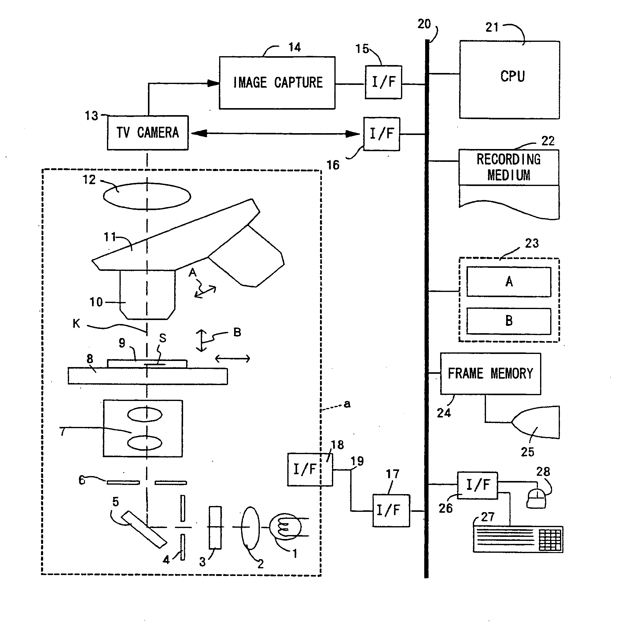
[0068]FIG. 3 is a flowchart of the actual capturing procedure used according to the basic principle according to the present invention. The capturing procedure is used by the control of the CPU 21 shown in FIG. 1. In FIG. 3, a low-powered objective lens is first used (S301).

[0069] In this process, when the operator inputs the “start of capture” button (not shown in the attached drawings) on the control screen displayed on the monitor 25, the CPU 21 controls the rotation of the revolver 11 of the microscope unit indicated by the broken lines a shown in FIG. 1 to set the lowest-powered objective lens of the objective lens 10.

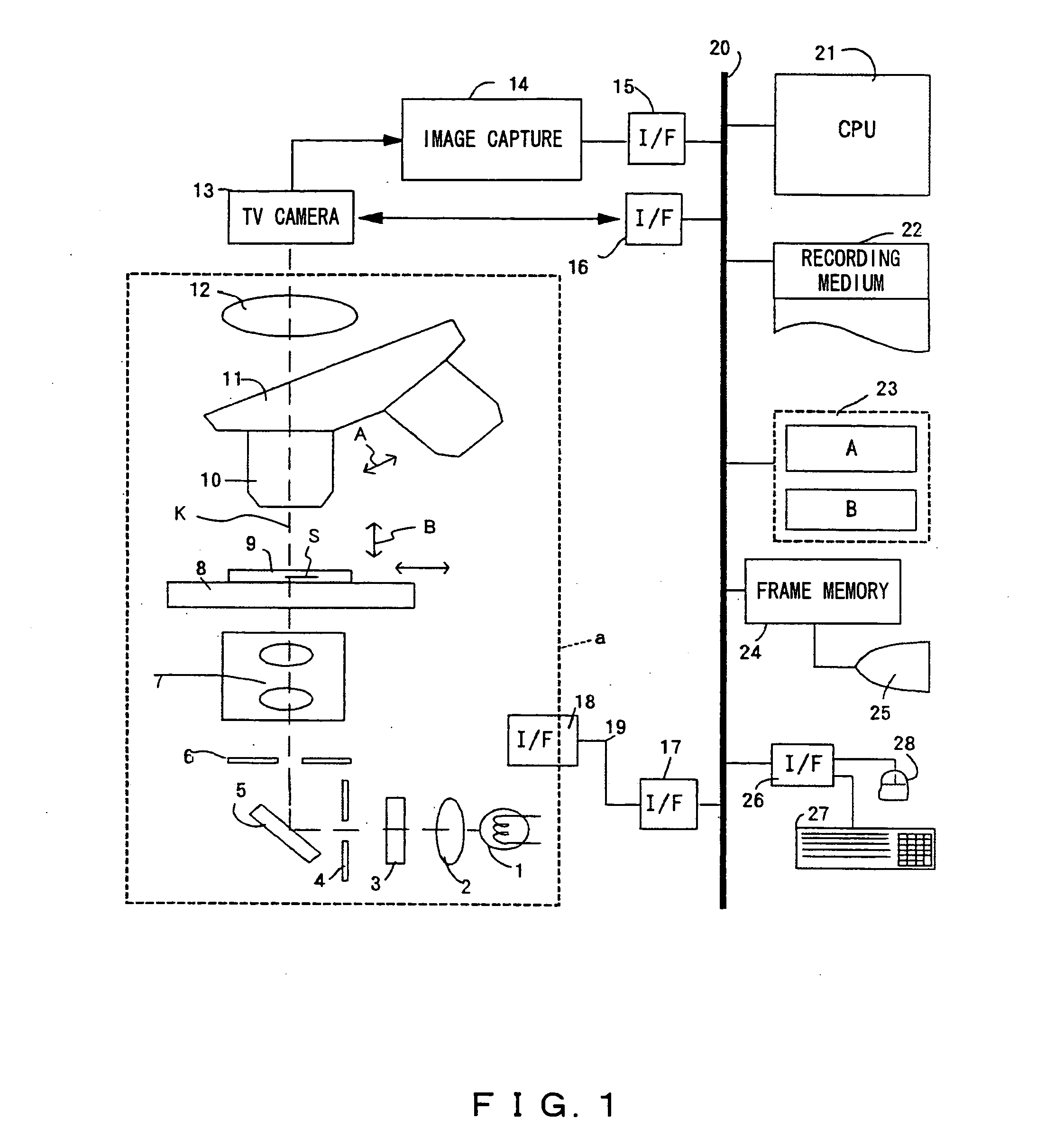
[0070] Then, the entire area of the slide glass 9 is scanned for each actual field size 29 (refer to FIG. 2A) of the low-powered objective lens using the above-mentioned low-powered objective lens to sequentially obtain the image information about a low-magnification actual field size of the stage coordinate sections (0, 0)˜(m, n) depending on the actual field si...

second embodiment

[0111] In another method, the low-powered objective lens can be replaced with a macro capture device to simultaneously capture the entire area of the slide glass 9 and divide the captured image information into high-powered objective lens conversion pixel size sections. This method is described below as the present invention.

[0112]FIG. 6 is a simple schematic diagram showing the capturing method according to the second embodiment of the present invention. In this embodiment, the entire area of the slide glass 9 is captured using a macro capture device 37 provided separate from the microscope unit indicated by the broken lines a shown in FIG. 1, and a position in which a sample image is contained is detected from image information 39 about the entire area of the slide glass 9 obtained in a macro capture area 38, and the sample image presence / absence coordinates obtained when the position is converted in a field size 40 of a high-powered objective lens are detected, thereby generating...

third embodiment

[0125]FIGS. 8A and 8B show the method of efficiently generating a, high-precision image in the present invention. FIG. 8A shows the sample S of the slide glass 9 being observed by any objective lens, the central observation position (Xc, Yc) of the sample S, and the field size Wobs×Hobs of the low-powered objective lens around the central observation position (Xc, Yc).

[0126]FIG. 8B(b) is an enlarged view of the field size Wobs×Hobs of a low-powered objective lens around the above-mentioned central observation position (Xc, Yc), and shows the state of dividing the field size Wobs×Hobs of the low-magnification by the field size 40 of a high-powered objective lens.

[0127] Assume that the observer operates an instruction button or a slide button on the control screen area (not shown in the attached drawings) of the monitor 25 using the keyboard 27 or the mouse 28 shown in FIG. 1 while observing the observation moving picture (partial image shown in FIG. 8A moved vertically and horizonta...


PUM


Abstract

A microscopic image capture apparatus and a microscopic image capturing method allow a wide-angle field and high-precision microscope digital image to be efficiently captured. First, the entire area of a slide glass on a stage is divided into field size sections (low-magnification sections) of a low-powered objective lens, the stage is sequentially transferred perpendicular to an optical axis, image information is obtained for each low-magnification section of the entire area, each low-magnification section is divided into high-magnification size sections (high-magnification sections), a high-magnification image is captured using a high-powered objective lens only on a high-magnification section including simultaneously in the high-magnification sections, a high-magnification image is generated by correctly maintaining the relative position between the obtained image information and the area of a high-magnification section which is not captured, and a high-magnification composite image information about a sample on the slide glass is generated.

Description

CROSS REFERENCE TO RELATED APPLICATION [0001] This application is a Divisional application of U.S. application Ser. No. 10 / 655,354, filed on Sep. 3, 2003, which is based upon and claims the benefit of priority from the prior Japanese Application No. 2002-263667, filed Sep. 10, 2002, the entire contents of which are incorporated herein by reference.BACKGROUND OF THE INVENTION [0002] 1. Field of the Invention [0003] The present invention relates to a microscopic image capture apparatus and a microscopic image capturing method for capturing a microscopic image of a sample, and more specifically to a microscopic image capture apparatus and a microscopic image capturing method for efficiently capturing a wide-angle field and high-precision microscopic digital image. [0004] 2. Description of the Related Art [0005] Conventionally, there has been a method of observing a microscopic image as a digital image. Generally, when a sample is observed, the range observed at a time mostly depends on...

Claims


Application Information

Patent Timeline
IPC IPC(8): G02B21/36G06T3/00
CPCG02B21/367
Inventor NAKAGAWA, SHUJI
Owner EVIDENT CORP
Why Eureka
Try Eureka