Tri-flow head assembly

Inactive Publication Date: 2005-09-01
BRENYER JEFFREY W
View PDF8 Cites 11 Cited by
  • Summary
  • Abstract
  • Description
  • Claims
  • Application Information

AI Technical Summary

Problems solved by technology

Various problems may arise as the material flow, if not balanced, may produce an unstable flow.
However, flow velocity is difficult to adjust absent a controlled increase in temperature and pressure which, if not regulated, can result in undesirable, unstable flows.
For example, an unstable resin flow may release gases, e.g., chlorine, resulting in stagnation, hardening and burning within the head assembly which results in undesirable imperfections.
The flow imbalances, if not corrected or compensated, can

Method used


Image

  • Tri-flow head assembly
  • Tri-flow head assembly
  • Tri-flow head assembly

Examples


Example

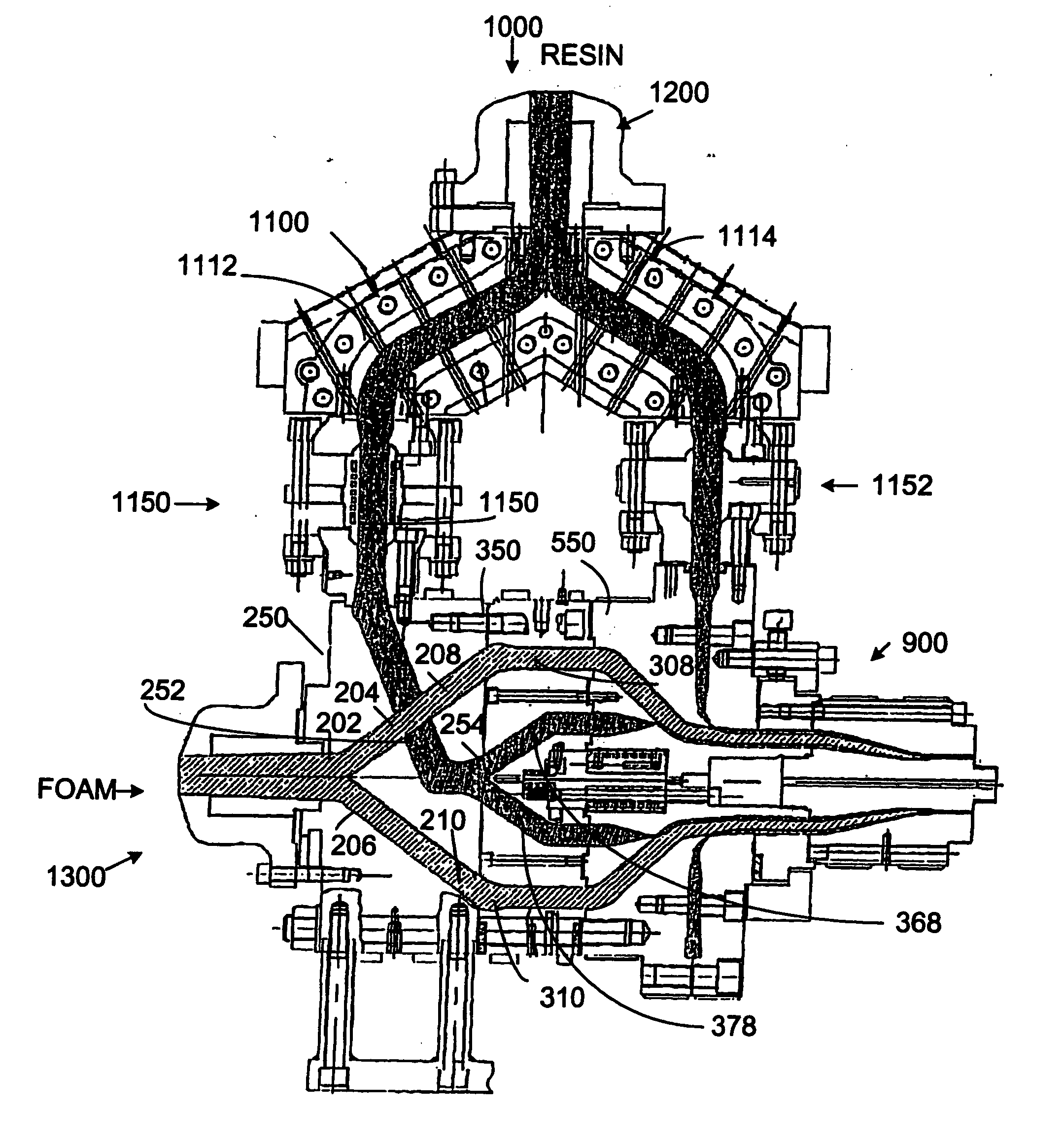
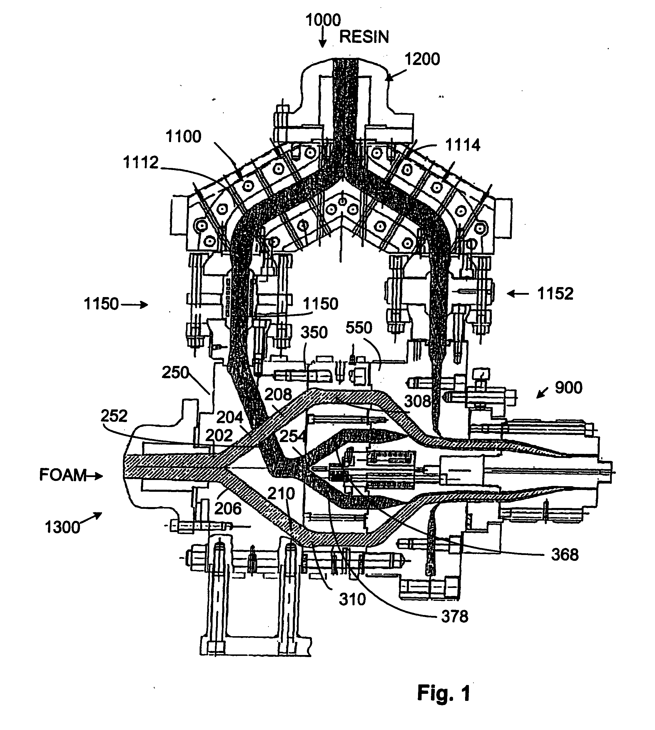
[0028] Turning more particularly to the drawings, FIG. 1 shows my head assembly as comprising a resin input assembly 1200, foamed resin input assembly 1300, a primary melt housing 250, a secondary melt housing 350, a scroll melt housing 550, and die housing 900.

[0029] The resin input assembly 1200 receives the melted resin from an upstream resin melt source 1000 which is delivered to a Y-block 1100 producing first and second resin paths 1112, 1114. Resin paths 1112, 1114 are directed through restrictors 1150, 1152 allowing for regulated control of the downstream resin melt flow.

[0030] The foamed resin input assembly 1300 directs an extruded foam from an upstream source into bore 202 in primary melt distributor block 250 (FIG. 2). This bore 202 branches 204, 206 (FIG. 3A) downstream for directing the foam from bore 202 to first 208 and second annular channels 210 transitioning to a full annular flow channel before the downstream face (FIG. 4) of the primary melt distributor housing...


PUM

PropertyMeasurementUnit
Flow rateaaaaaaaaaa

Abstract

A head assembly for presenting a three layer material flow includes primary and secondary housings for presenting a first interior layer and a second intermediate layer of the three layer flow. A downstream melt distributor melds the first and second material layers into a combined material flow for deposit of a third exterior layer about the combined flow. The melt distributor includes a sinuous channel for directing the material of the outer layer into points of discharge about the combined material flow. A scroll-like distributor communicates with the discharge points for directing the third material into an annular path about the combined flow, and a subsequent melding of the third material with the combined flow. The resulting three layer flow is directed to a downstream die assembly.

Description

BACKGROUND OF THE INVENTION [0001] This invention relates to an extrusion head assembly and, more particularly, to an assembly which efficiently presents a concentric, multilayered material flow to a downstream die assembly. [0002] In order to produce a tri-layered material product, three layers of the material, e.g., an extruded thermoplastic resin / resin combination or three resin material layers, must be presented. The head assembly receives resin and resin with foaming agent from upstream sources, which are then heated, combined and directed to a downstream die assembly. Upon passage of the flow through the die assembly, a multi-layered product is presented having exterior and interior resin layers from the same source with a foamed layer therebetween. [0003] Various problems may arise as the material flow, if not balanced, may produce an unstable flow. In order to achieve uniformity in the layers, the flow velocity must be controlled. However, flow velocity is difficult to adjus...

Claims


Application Information

Patent Timeline
IPC IPC(8): B29C48/09B29C48/335B29C48/34
CPCB29C47/0023B29C47/025B29C47/065B29C47/705B29C47/261B29C47/28B29C47/26B29C48/30B29C48/09B29C48/154B29C48/21B29C48/335B29C48/336B29C48/34B29C48/705
Inventor BRENYER, JEFFREY W.
Owner BRENYER JEFFREY W
Why Eureka
Try Eureka