
Method and apparatus for electrophotographic image forming capable of using a toner enhancing image quality and cleanability, and the toner used in the image forming

a technology of electrophotographic image and toner, which is applied in the field of electrophotographic image forming and toner used in image forming, can solve the problems of insufficient evaluation of differences in inability to evaluate the fluidity of fine toner particles, and complex structure, etc., to achieve superior enhance cleanability, and improve image quality and cleanability.

Inactive Publication Date: 2005-09-01
RICOH KK
View PDF16 Cites 19 Cited by
  • Summary
  • Abstract
  • Description
  • Claims
  • Application Information

AI Technical Summary

Benefits of technology

The present invention provides an electrophotographic image forming apparatus that uses a toner with minuscule spherical particles for superior image quality and cleanability without deteriorating the cleaning blade. The toner has the properties of being cleaned by the cleaning blade, maintaining superior image quality and enhancing cleanability. The toner used in the invention includes a binder resin, colorant, and other components. The toner powder layer formed by the toner satisfies an inequality and has a specific shape. The use of this toner results in an image forming apparatus that produces high-quality images consistently.

Problems solved by technology

Therefore, difference of fluidity of fine toner particles could not be evaluated.
Since such smaller and more functional toner has a more complex structure, detailed controls in toner manufacturing are required.
Therefore, the above-described technique has not been sufficient for evaluating differences of fluidity of toner.
In addition, the above-described technique has not shown porosities of toner without additive.
However, when a toner particle in which an average particle diameter distribution of toner is equal to or less than 7 μm or a toner particle having a spherical shape is used for high image quality, it is difficult for the above-described methods to obtain a margin of cleanability.
Therefore, it is difficult to clean the toner particle remaining on, for example, a surface of an image bearing member.
Such toner particle having a minuscule spherical form may easily roll into a space between an image bearing member and a cleaning member, resulting in a cleaning failure such as black dots on a background of an image.
When a cleaning blade having an edge that may be abraded or cracked is used, the cleaning failure may easily occur.
With the deformed cleaning blade, the image bearing member contacting with the cleaning blade may be abraded to change the surface of the image bearing member to be odd-shaped or indented, thereby causing a cleaning failure on the surface of the image bearing member.
However, when the toner particles easily roll into a space between the cleaning blade and an image bearing member, the constant amount of toner supplied to the cleaning blade may facilitate abrasion of the cleaning blade.
However, this technique is not sufficient to obtain a better cleanability and durability when a small toner particle having a spherical form is used.
However, a desired cleanability is not sufficiently achieved with the above-described technique.
As previously mentioned, when residual spherical toner particles may cause the cleaning failure by falling to a space between the cleaning blade and the image bearing member, resulting in poor image quality.
However, those techniques may cause an excess or shortage of the cleaning auxiliary agents, and result in a lack of stability.
However, while the cleaning blade is contacting the image bearing member with high pressure, the surface of the image bearing member may easily be abraded, and may not have high durability.

Method used


Image

  • Method and apparatus for electrophotographic image forming capable of using a toner enhancing image quality and cleanability, and the toner used in the image forming
  • Method and apparatus for electrophotographic image forming capable of using a toner enhancing image quality and cleanability, and the toner used in the image forming
  • Method and apparatus for electrophotographic image forming capable of using a toner enhancing image quality and cleanability, and the toner used in the image forming

Examples


Embodiment Construction

[0056] In describing preferred embodiments illustrated in the drawings, specific terminology is employed for the sake of clarity. However, the disclosure of this patent specification is not intended to be limited to the specific terminology so selected and it is to be understood that each specific element includes all technical equivalents that operate in a similar manner.

[0057] Referring now to the drawings, wherein like reference numerals designate identical or corresponding parts throughout the several views, preferred embodiments of the present invention are described.

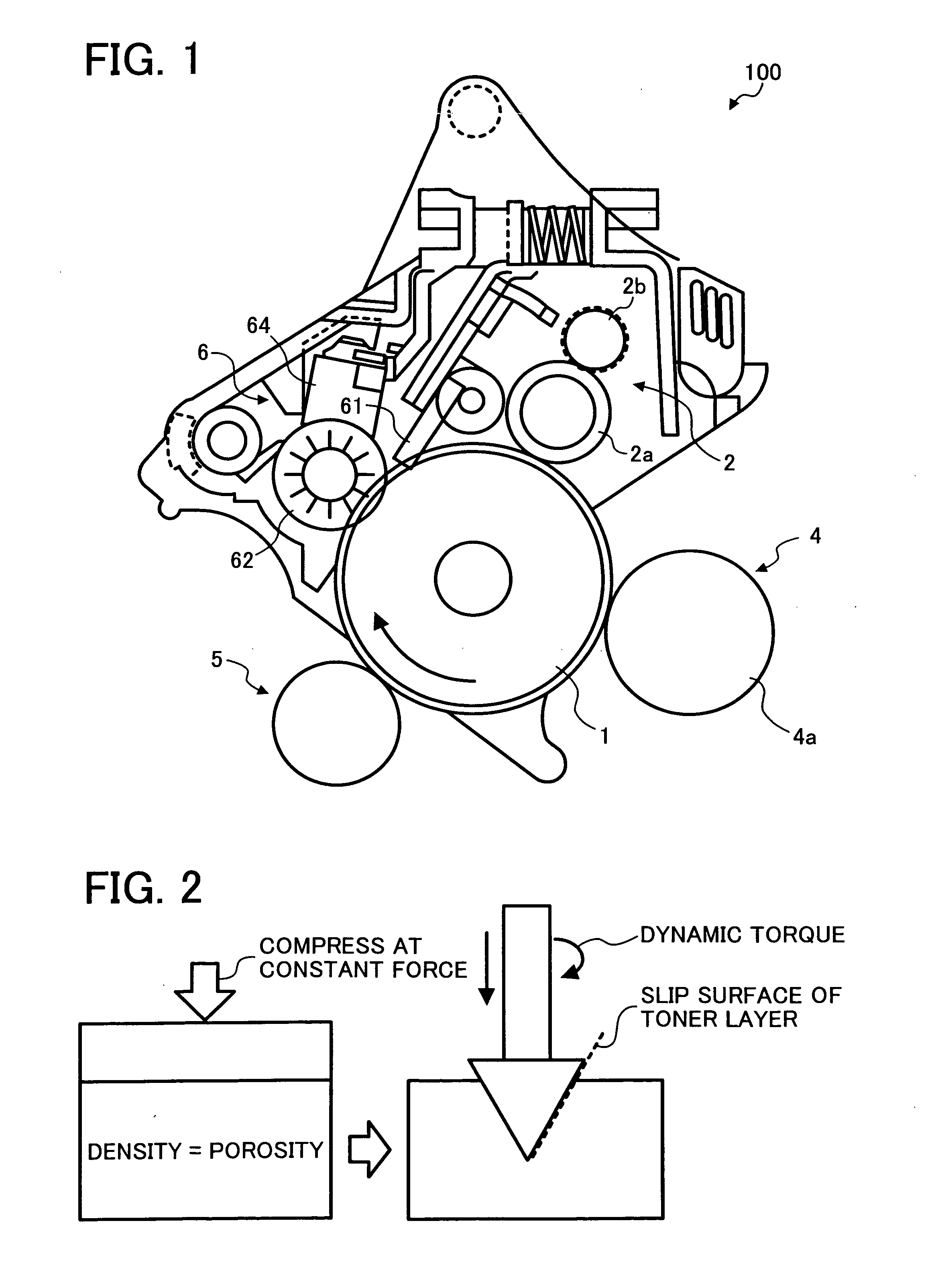
[0058] Referring to FIG. 1, a schematic structure of an image forming unit 100 of an image forming apparatus (not shown) according to an exemplary embodiment of the present invention is described.

[0059] The image forming unit 100 of FIG. 1 includes a photoconductive element 1, a charging unit 2, a developing unit 4, a transfer unit 5, a cleaning unit 6, a writing unit (not shown), and a fixing unit (not shown). ...


PUM


Abstract

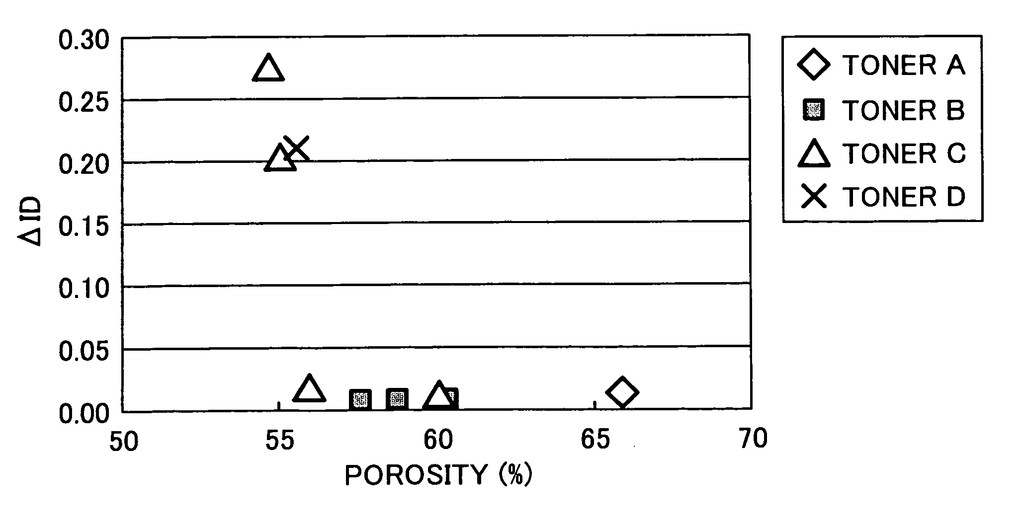
An image forming apparatus performs electrophotographic image forming using a toner and includes an image bearing member configured to bear an electrostatic latent image on a surface thereof, a developing mechanism configured to develop the electrostatic latent image in to a toner image by using a toner, a transfer mechanism configured to transfer the toner image from the image bearing member to an image receiver, a cleaning mechanism including a cleaning blade and configured to remove a residual toner on the image bearing member after toner image is transferred to the image receiver. The toner includes a binder resin and a colorant, forms a toner powder layer, and satisfies an inequality Y≧−0.05X+0.029, in which “X” expresses a porosity of the toner powder layer after uniformly compressed at a constant force and “Y” expresses a torque value obtained by rotatably sticking a conical rotor into the toner powder layer.

Description

CROSS REFERENCE TO RELATED APPLICATIONS [0001] The present application claims priority under 35 U.S.C. § 119 to Japanese Patent Application No. 2004-042210 filed on Feb. 19, 2004 in the Japanese Patent Office, the entire contents of which are hereby incorporated herein by reference. BACKGROUND OF THE INVENTION [0002] 1. Field of the Invention [0003] The present invention relates to a method and apparatus for electrophotographic image forming and a toner used in the image forming. In particular, the present invention relates to a method and apparatus for electrophotographic image forming capable of using a toner enhancing image quality and cleanability without causing deterioration of a cleaning blade, and a toner used in the image forming enhancing image quality and cleanability. [0004] 2. Discussion of the Background [0005] In a background image forming apparatus, an electrophotographic image forming method is widely used for copiers, facsimile machines, laser printers, etc. The ba...

Claims


Application Information

Patent Timeline
Patent Type & Authority Applications(United States)
IPC IPC(8): G03G9/08G03G9/087G03G21/10
CPCG03G9/0821
Inventor KOIKE, TOSHIOOJIMI, TOKUYATAWADA, TAKAAKISHINTANI, TAKESHIARAI, YUJIYONEDA, TAKUZUKAWASUMI, MASANORITOMITA, MASAMIUMEMURA, KAZUHIKOAMEMIYA, KEN
Owner RICOH KK
Learn More