Produce conveying and sizing equipment

Active Publication Date: 2019-05-23
REED LORIN
View PDF8 Cites 5 Cited by
  • Summary
  • Abstract
  • Description
  • Claims
  • Application Information

AI Technical Summary

Benefits of technology

The present invention provides better equipment for sorting and sizing produce using multiple conveyor rails and individual pucks that move along with the rails. The motion is caused by rotatable sprocket wheels at the beginning of each rail, instead of continuous chains or belts. Additionally, the invention includes a new actuation system for moving produce off the sorting conveyor cups and into their appropriate storage area, which uses electromagnets. This improvement makes the produce sorting, sizing, and conveying systems more durable and easy to clean.

Problems solved by technology

Unfortunately, the continuous chains, the wires, the cross beams and the solenoids themselves provide numerous irregular openings and surfaces where contamination and debris may accumulate over time, especially when thousands of pieces of produce travel through such systems on a typical day.
As a result, it is difficult to completely clean these systems.
This increases the risk that contamination, including listeria or other pathogens, may be transferred to the cups, to the produce, and to consumers of the produce.
Conventional sorting / sizing systems also suffer from maintenance and cleaning challenges.
Existing conveying systems typically use roller chains to drive the system, which tend to stretch over time, resulting in variance in the timing and movement of the conveyor, and the cups or other support structures that are driven along the conveyor.
Additionally, the roller chain is susceptible to rust if the conveying system is washed with water or aqueous solution, resulting in deterioration of the function of the conveying system and needed repairs.
Deterioration and variance in the operation of the conveying system can easily lead to errors in sorting the produce, since such systems work at high speeds.

Method used


Image

  • Produce conveying and sizing equipment
  • Produce conveying and sizing equipment
  • Produce conveying and sizing equipment

Examples


Embodiment Construction

[0070]Reference will now be made in detail to certain embodiments of the invention, examples of which are illustrated in the accompanying drawings. While the invention will be described in reference to these embodiments, it will be understood that they are not intended to limit the invention. To the contrary, the invention is intended to cover alternatives, modifications, and equivalents that are included within the spirit and scope of the invention as defined by the claims. In the following disclosure, specific details are given to provide a thorough understanding of the invention. However, it will be apparent to one skilled in the art that the present invention may be practiced without these specific details.

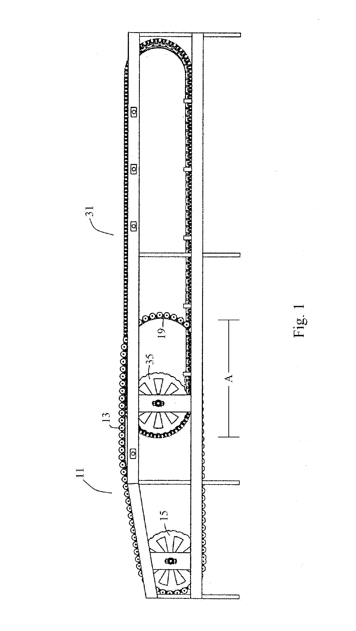
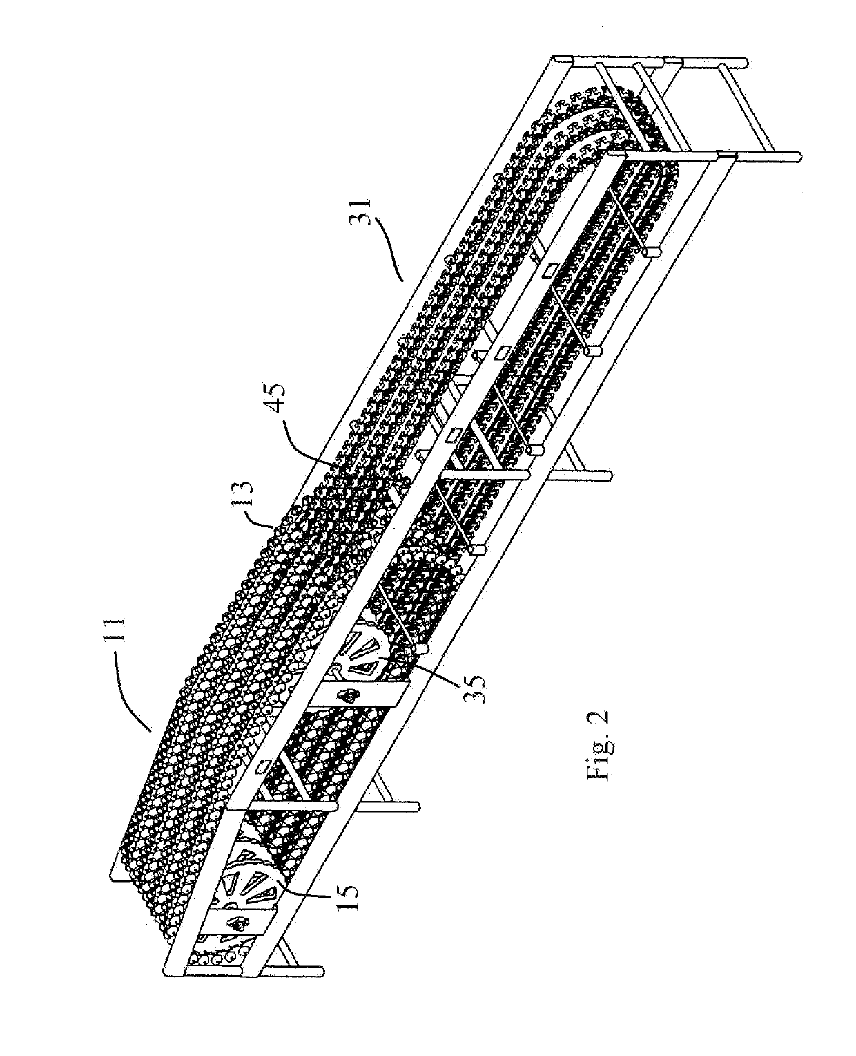
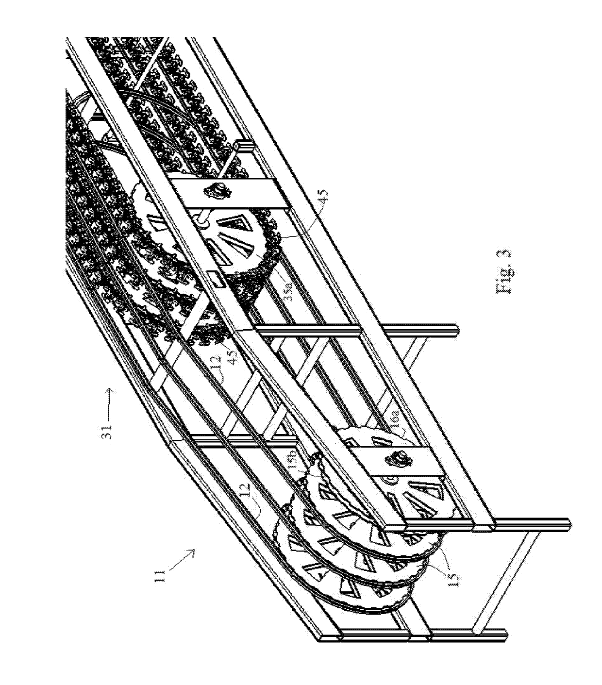
[0071]Referring to the drawings wherein like reference characters designate like or corresponding parts throughout the several views, it is seen that the present invention includes various embodiments of conveying and sorting systems utilizing a plurality of continuous rails w...


PUM


Abstract

The present invention includes conveying and sorting systems utilizing a plurality of continuous rails which support a plurality of sliding pucks that are urged forward using a plurality of sprocket wheels, and which utilize magnetically operated activation components for causing produce to be selectively dropped from cups carried by the pucks into sorting bins. The structures for the conveying and actuating components of the systems have smooth external surfaces reducing potential contamination by bacteria, contaminants and debris, thereby making them easily accessible for cleaning, and allowing for longer continuous operation times and higher efficiency.

Description

FIELD OF THE INVENTION[0001]The present invention relates to produce conveying and sizing equipment, and more particularly to improved produce conveying, sorting and sizing apparatus that is less susceptible to contamination and is easily cleaned, and methods of using the same.BACKGROUND[0002]Conventional produce handling and sorting / sizing equipment include cups or other structures that travel along pathways in the conveying and sorting / sizing system and support individual pieces of produce as they are carried through the system. Typically, these systems have a photographic zone, a weighing zone and a sorting / sizing zone. The produce pieces are placed on individual cups, and first passed through the photographic zone to evaluate the condition and quality of the produce, and then passed through a weighing zone. The produce pieces are then transported on a conveyor from the weighing zone into an appropriate sorting / sizing area where they are separated according to size, shape, color,...

Claims


Application Information

Patent Timeline
IPC IPC(8): B65G23/08B65G43/00
CPCB65G23/08B65G43/00B65G47/962B65G2201/0211B65G35/08B65G37/005B65G15/58B65G23/06B65G17/12B65G17/18
Inventor REED, LORIN
Owner REED LORIN
Why Eureka
Try Eureka