Water jet-processing machine

Active Publication Date: 2005-09-01
DISCO CORP
View PDF11 Cites 11 Cited by
  • Summary
  • Abstract
  • Description
  • Claims
  • Application Information

AI Technical Summary

Benefits of technology

[0012] The water jet-processing machine of the present invention detects a processing sound wave generated by processing water ejected from the nozzle to the workpiece and controls the moving means for moving the nozzle in a direction perpendicular to the holding surface of the workpiece holding table based on the detection signal. Therefore, even when the workpiece curves, the interval between the squirt hole of the nozzle and the surface of the workpiece can be always maintained at a predetermined range. Consequently, even when the workpiece curves, it can be cut highly accurately without fail and also, a problem that the nozzle contacts the workpiece to damage its surface can be eliminated.

Problems solved by technology

This dicing machine comprises a cutting blade having an annular abrasive grain layer and cuts the CSP substrate along the streets by moving this cutting blade relative to the CSP substrate along the streets of the CSP substrate while rotating the cutting blade so as to divide it into individual chip size packages (CSP) When the CSP substrate is cut with the cutting blade, however, a problem arises in that burrs are formed on the connection terminals to cause a short circuit between adjacent connection terminals, thereby reducing the quality and reliability of a chip size package (CSP).
Further, when not only the CSP substrate but a workpiece such as a semiconductor wafer is cut with the cutting blade, another problem occurs that fine chips are adhered onto the front surface of the workpiece, thereby contaminating the workpiece.
That is, when processing is carried out by setting the interval between the squirt hole of the nozzle and the front surface of the workpiece to, for example, 50 μm, if the interval becomes larger than 100 μm, a problem arises that the processing accuracy will become unstable, whereby the cut grooves will become nonuniform in width, or an uncut area will be produced, or abrasive grains will be scattered to damage the surface of the workpiece, while if the interval between the squirt hole of the nozzle and the surface of the workpiece is smaller than the above set value, a problem occurs that the nozzle may contact with the workpiece to damage its surface.

Method used


Image

  • Water jet-processing machine
  • Water jet-processing machine
  • Water jet-processing machine

Examples


Embodiment Construction

[0025] Preferred embodiments of a water jet-processing machine constituted according to the present invention will be described in detail herein under with reference to the accompanying drawings.

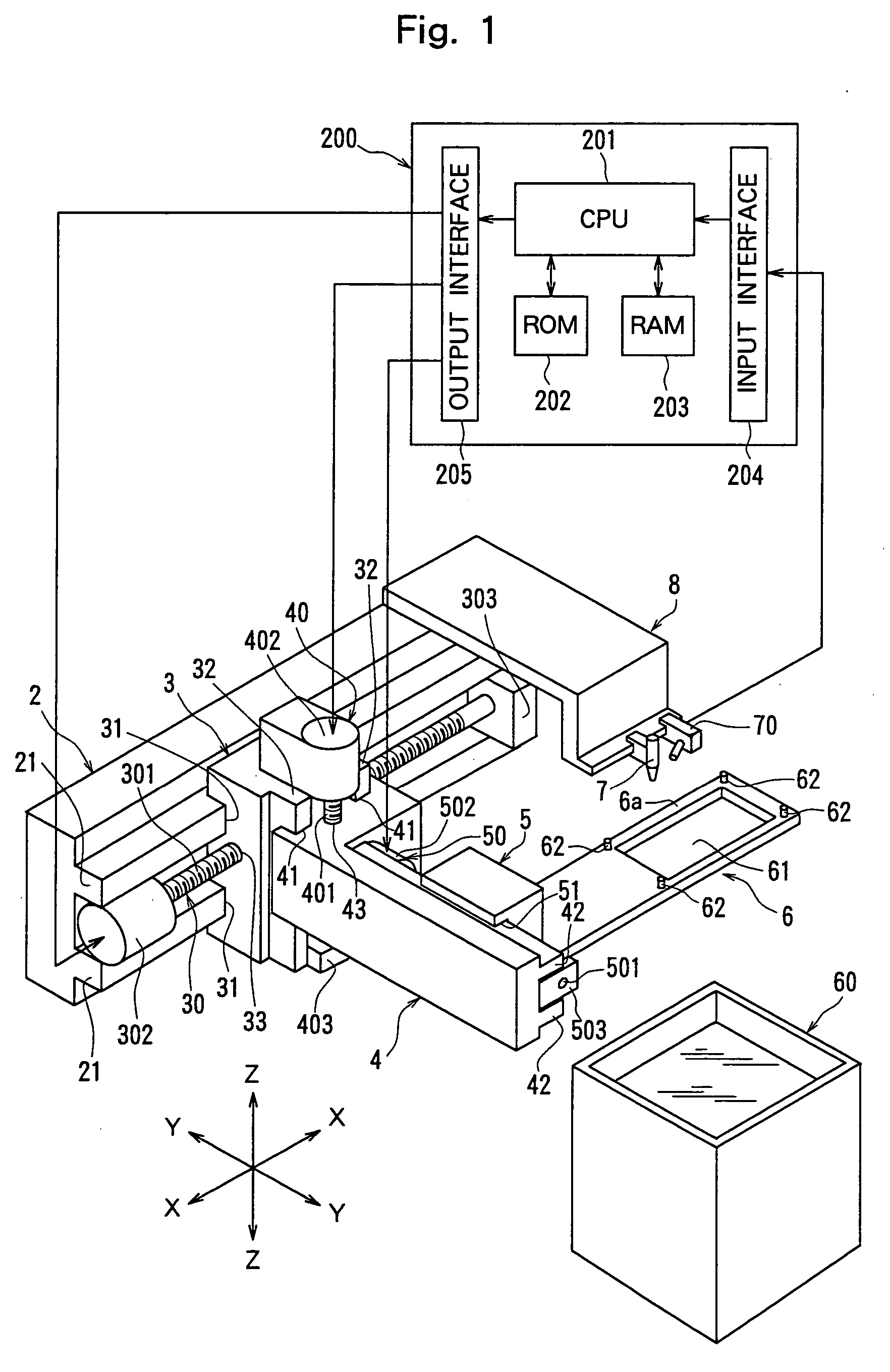
[0026]FIG. 1 is a perspective view of the principal section of a water jet-processing machine constituted according to the present invention. The water jet-processing machine shown in FIG. 1 comprises a stationary base 2, a first movable base 3, a second movable base 4 and a third movable base 5. A pair of guide rails 21 and 21 extending parallel to each other in the direction indicated by an arrow X are formed on the flank side of the stationary base 2.

[0027] The first movable base 3 has a pair of to-be-guided grooves 31 and 31 that are formed on one flank opposed to the above stationary base 2 in the direction indicated by the arrow X and are slidably fitted to the pair of guide rails 21 and 21 formed on the stationary base 2, and a pair of guide rails 32 and 32 that formed on the other ...


PUM

PropertyMeasurementUnit
widthaaaaaaaaaa
widthaaaaaaaaaa
diameteraaaaaaaaaa

Abstract

A water jet-processing machine comprising a workpiece holding table having a holding surface for holding a workpiece, a nozzle for emitting a jet of processing water to the workpiece held on the holding surface of the workpiece holding table, a processing water supply means for supplying processing water containing abrasive grains to the nozzle and a moving means for moving the nozzle in a direction perpendicular to the holding surface of the workpiece holding table, wherein the machine further comprises processing sound wave detection means for detecting a processing sound wave generated by processing water ejected from the nozzle to the workpiece and a control means for controlling the moving means based on a detection signal detected by the processing sound wave detection means.

Description

FIELD OF THE INVENTION [0001] The present invention relates to a water jet-processing machine for cutting a plate-like workpiece such as a semiconductor wafer by emitting a jet of high-pressure water to the workpiece. DESCRIPTION OF THE PRIOR ART [0002] In the production process of a semiconductor device, individual semiconductor chips are manufactured by forming a circuit such as IC, LSI or the like in a large number of areas arranged in a lattice pattern on the front surface of a substantially disk-like semiconductor wafer, and dicing the semiconductor wafer into the areas having each a circuit formed thereon along predetermined cutting lines called “streets”. The thus divided semiconductor chips are packaged, and widely used in electric appliances such as cellular phones, personal computers or the like. [0003] Lighter and smaller electric appliances such as cellular phones, personal computers or the like are now in demand, and packaging technologies called “Chip Size Package (CSP...

Claims


Application Information

Patent Timeline
Patent Type & Authority Applications(United States)
IPC IPC(8): B24C1/04B24C5/02B24C7/00
CPCB24C7/0007B24C1/045
Inventor SEKIYA, KAZUMA
Owner DISCO CORP
Why Eureka
Try Eureka