
Receiver and electronic apparatus including receiver

a technology of electronic equipment and receiver, which is applied in the direction of pulse technique, anti-theft device, instruments, etc., can solve the problems of inability to meet the different communication performance, inability to ensure the communication performance (communication range) required of the rke system, and high cost of the electronic equipment installed by the vehicle, so as to enhance the system response and enhance the sensitivity

Inactive Publication Date: 2005-09-01
DENSO CORP
View PDF7 Cites 45 Cited by
  • Summary
  • Abstract
  • Description
  • Claims
  • Application Information

AI Technical Summary

Benefits of technology

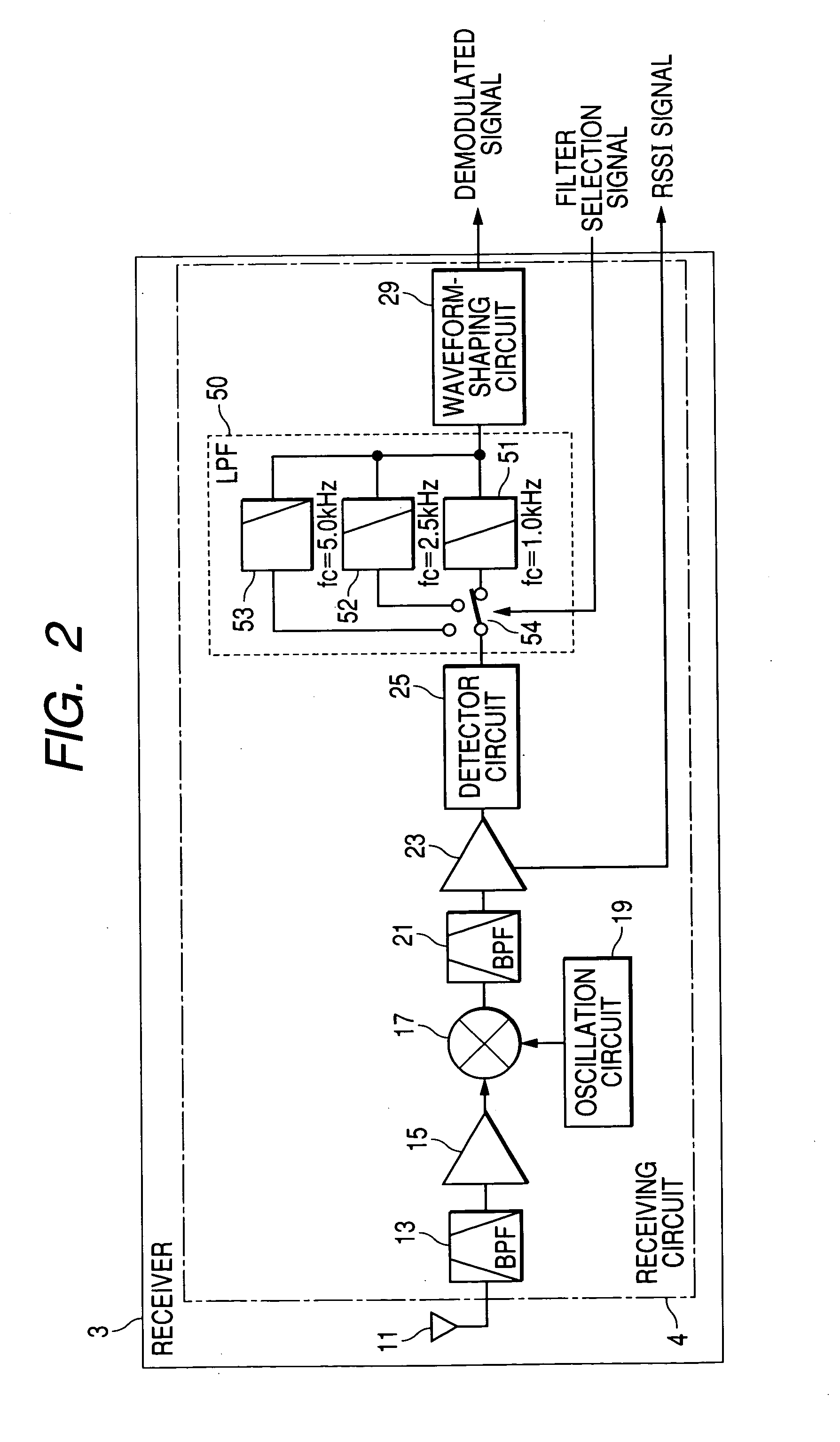
[0023] With this configuration, it becomes possible to enhance the sensitivity (communication range) when receiving a radio wave for a system having a low communication bit rate (low baseband signal frequency), to enhance the system response when receiving a radio wave for a system having a high communication bit rate, and to set the sensitivity and the system response at moderate levels when receiving a radio wave for a system having a moderate communication bit rate.
[0024] With the receiver of the invention, control systems configured to receive different kinds of radio waves that have the same frequency band, are modulated by the same modulation scheme, and are different in a baseband-signal frequency can be implemented with a relatively smaller circuit configuration, because the different kinds of the radio waves can be received by the single receiver, and a single control device can perform radio wave receiving operations for all of the different kinds of the radio waves without difficulty.

Problems solved by technology

For the reason described above, the vehicle-installed electronic apparatus has been expensive and large in size.
However, in this case, it is not possible to satisfy the different communication performances (communication range and system response) required of the three different systems.
However, in this setting, the communication performance (communication range) required of the RKE system cannot be ensured.

Method used


Image

  • Receiver and electronic apparatus including receiver
  • Receiver and electronic apparatus including receiver
  • Receiver and electronic apparatus including receiver

Examples


Embodiment Construction

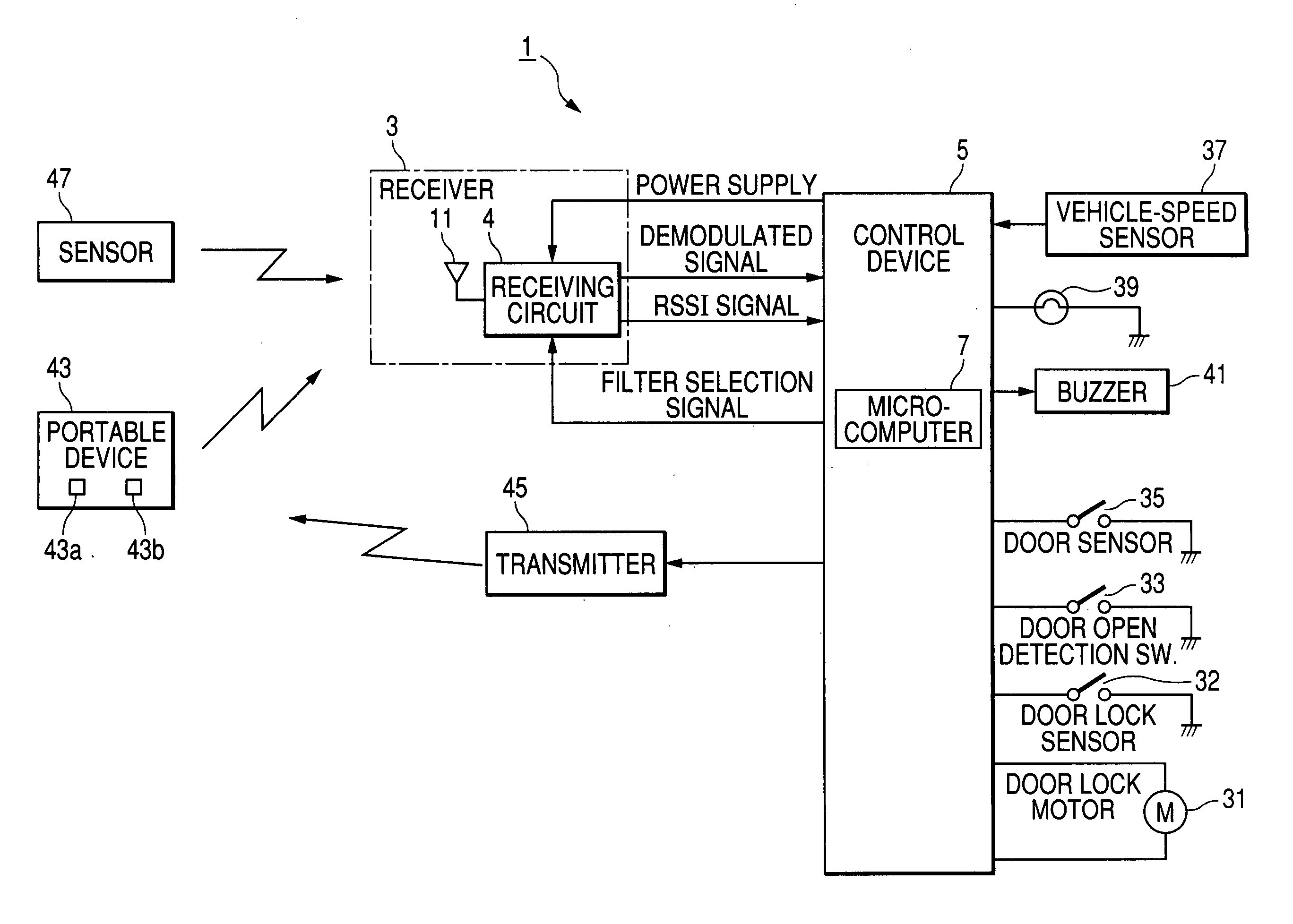
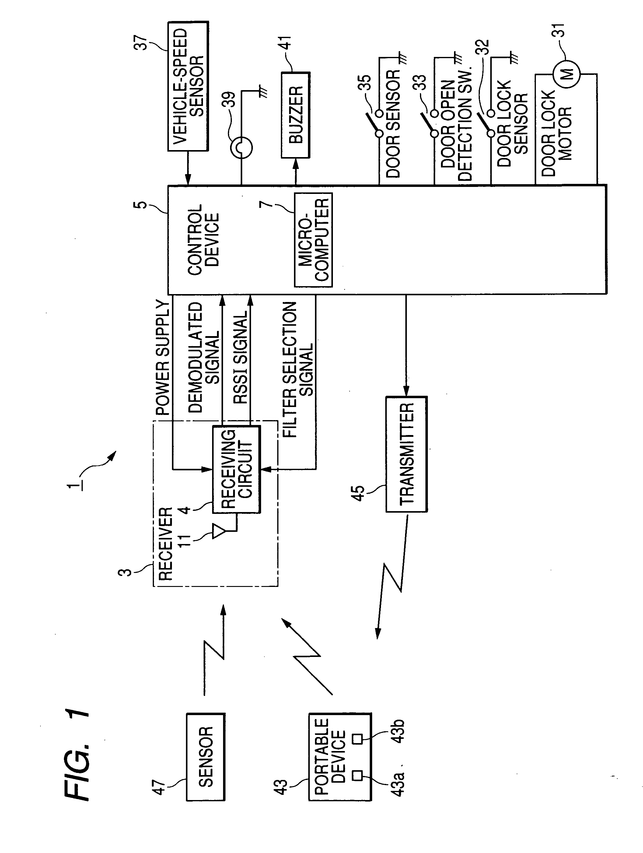
[0038]FIG. 1 is a block diagram schematically showing a structure of a vehicle-installed electronic apparatus including a receiver according to an embodiment of the invention.

[0039] As shown in this figure, the electronic apparatus 1, which is installed in a vehicle for performing processes for the RKE system (remote keyless entry system), SMART system (smart keyless entry system) and TPM system (tire air pressure monitoring system), includes a receiver 3 for receiving three kinds of radio waves for these three systems, and a control device 5 for performing control processings for these systems. The control device 5 has a microcomputer 7 controlling the entire operation of the control device 5.

[0040] The control device 5 is connected to the receiver 3, a door lock motor 31 acting to lock and unlock the door of the vehicle, a door lock sensor 32 for detecting a lock / unlock state of the door, a door-open detecting switch 33 for detecting an open / close state of the door, a door senso...


PUM


Abstract

The receiver includes an antenna for receiving a radio wave transmitted from a communication target, a demodulator extracting a baseband signal from the radio wave received by the antenna, and a filter device for low-pass filtering the baseband signal extracted by the demodulator. The filter device is configured to vary a cut-off frequency thereof in accordance with a command signal received from outside the receiver.

Description

CROSS-REFERENCE TO RELATED APPLICATION [0001] This application is related to Japanese Patent Applications No. 2004-41758 filed on Feb. 18, 2004, the contents of which are hereby incorporated by reference. BACKGROUND OF THE INVENTION [0002] 1. Field of the Invention [0003] The present invention relates to a receiver and an electronic apparatus including the receiver. [0004] 2. Description of Related Art [0005] Control systems having an electronic apparatus which is installed in a vehicle to perform control of electric loads and information processings through communication with the outside have been in practical use. The most common one of such control systems is a remote keyless entry system (abbreviated as “RKE system” hereinafter). In this system, lock / unlock of doors of a vehicle is performed when an electronic apparatus installed in the vehicle receives and validates a radio wave containing information specific to the vehicle, which is transmitted from a portable device carried ...

Claims


Application Information

Patent Timeline
Patent Type & Authority Applications(United States)
IPC IPC(8): B60R25/01B60C23/04B60R25/10B60R25/24B60R25/31B60R25/32B60R25/34E05B49/00G08C17/02H04B1/00H04B1/06H04B1/16H04B1/26H04B1/30H04Q9/00
CPCB60C23/0418H04B1/30B43K21/04B43K21/006
Inventor KATSUTA, YOSHINORI
Owner DENSO CORP
Learn More