
Method and device for determining the position of terminal in a cellular mobile radio network

a technology of cellular mobile radio and terminal, which is applied in the direction of selection arrangements, electrical equipment, wireless communication, etc., can solve the problems of inexact service area identification methods and disadvantages, and achieve the effect of minimizing the number of additional devices or equipment required and high accuracy

Inactive Publication Date: 2005-09-01
SIEMENS AG
View PDF5 Cites 27 Cited by
  • Summary
  • Abstract
  • Description
  • Claims
  • Application Information

AI Technical Summary

Benefits of technology

"The invention proposes a method and arrangement for determining the position of a terminal in a cellular mobile radio network with high accuracy and without the need for additional equipment or modifications to the network infrastructure. The method involves requesting measurement data from the terminal and using this data, together with field strength models, to compute the position of the terminal. This approach allows for the use of existing network infrastructure and minimizes the impact on the network. The method can be implemented with a single processing computer in the network and requires only minimal additional payload channel network traffic. The measurement data can include the field strength of the base station and the cell ID of the cell servicing the terminal, which can be used to determine the geographical position of the terminal. The method can be accessed through an IP data connection, which simplifies communication and reduces costs. Overall, the invention provides a more efficient and cost-effective way to determine the position of a terminal in a mobile network."

Problems solved by technology

In rural areas with large cells this SAI (Service Area Identity” method is however too inexact for numerous applications.
Although these OTD (Observed Time Difference) methods allow accuracies of the order of magnitude of 30 m, the major outlay is a disadvantage which manifests itself for the network operator in the need to install a plurality of LMUs.

Method used


Image

  • Method and device for determining the position of terminal in a cellular mobile radio network
  • Method and device for determining the position of terminal in a cellular mobile radio network
  • Method and device for determining the position of terminal in a cellular mobile radio network

Examples


Embodiment Construction

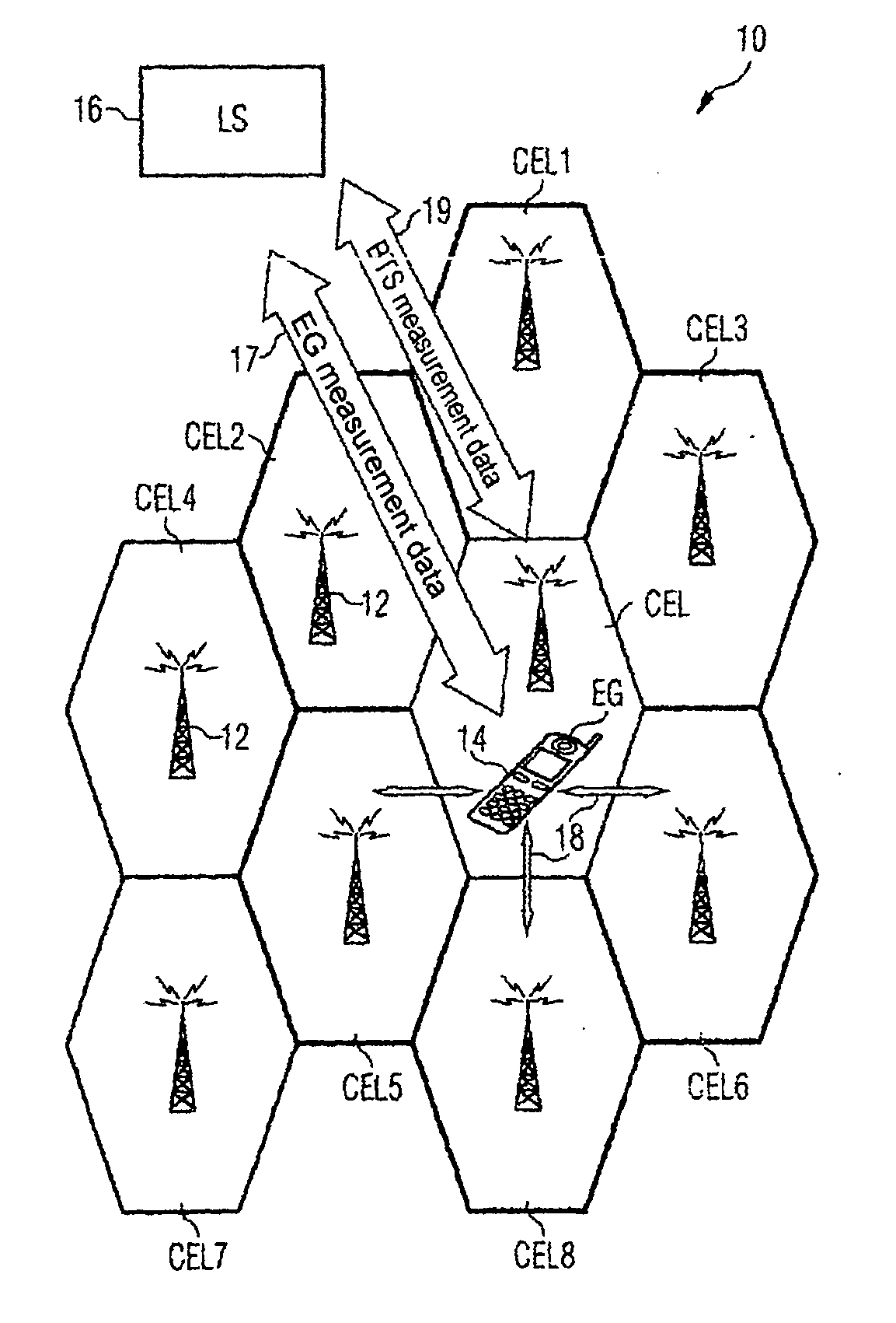
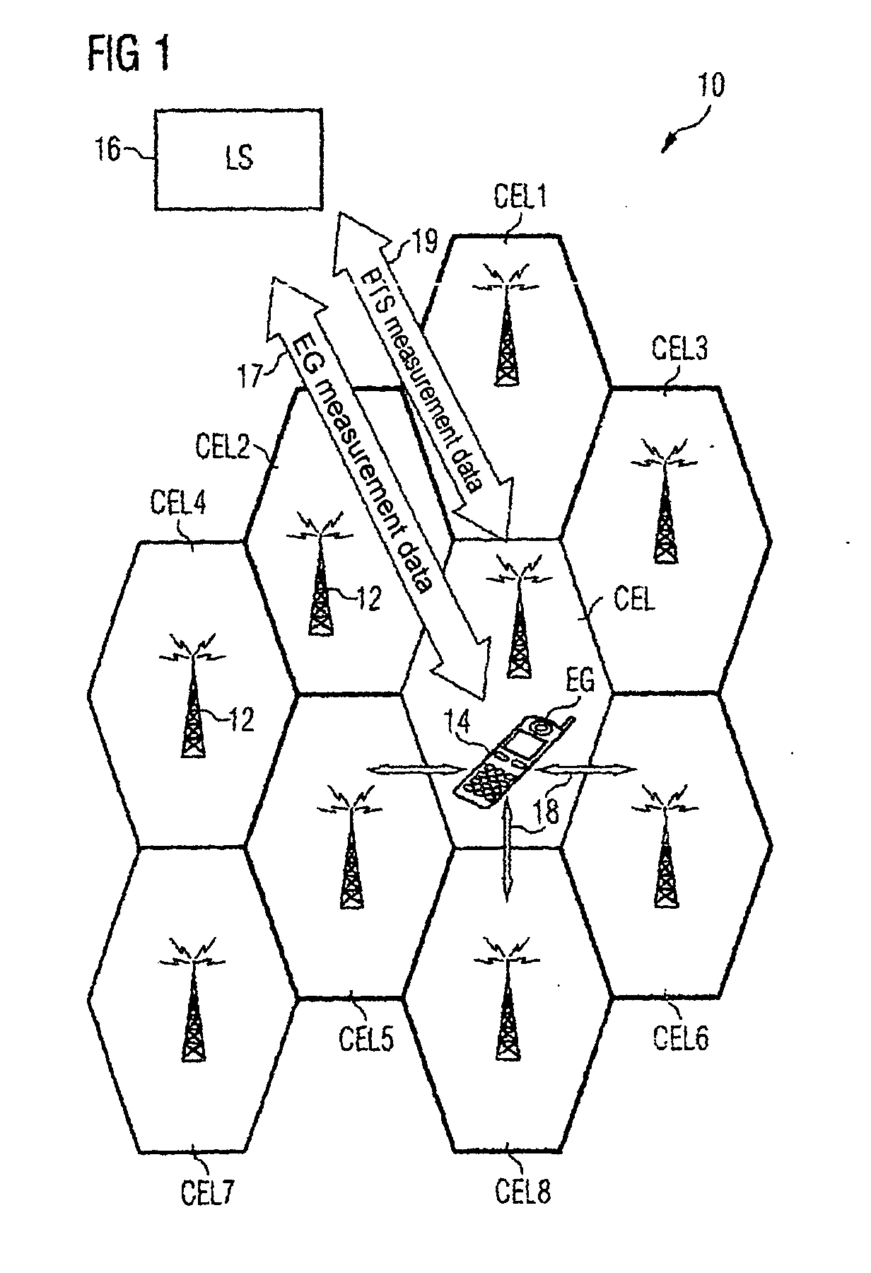
[0046] The mobile radio network 10 shown schematically in FIG. 1 can be a GSM, GPRS, UMTS or also TETRA (TErrestial TRunked Radio) network or similar cellular mobile radio network. This network 10 features a plurality of cells CEL and CEL1-CEL8. Each of these cells is serviced by one of the symbolically indicated base stations 12. The schematic diagram of FIG. 1 shows all cells as having the same size and form, but in actual fact the mobile radio cells can have quite different dimensions. The base stations 12 (i.e. the BTSs of the base stations) do not have to be located in the center of a cell but, depending on the beam form of the transmit antenna of the base station can be located at one edge or corner of the cell to be serviced for example.

[0047] In a cell CEL of the mobile radio network 10 there is a terminal 14. After the terminal 14 is switched on a suitable radio cell must first be found for the service provision before the user can begin and accept calls. For this purpose ...


PUM


Abstract

Method for determining the position of a terminal (14) in a cellular mobile radio network (10). with network measurements being executed in the terminal (14) for selection of a service cell (CEL), with the following steps: transfer (S2) of a measurement data request message from a position determination server (16) to the terminal (14), reading out (S3) of measurement data determined by the network measurements from a measurement data memory (40) in the terminal (14) in response to the request message, transfer (S4) of a response message with the read out measurement data from the terminal (14) to the position determination server (16), calculation (S5) of the position of the terminal (14), based on the measurement data transferred, in the position determination server (16).

Description

CROSS REFERENCE TO RELATED APPLICATIONS [0001] This application claims priority to the German application No. 10 2004 009 291.5, filed Feb. 26, 2004 which is incorporated by reference herein in its entirety. FIELD OF INVENTION [0002] The invention relates to a method and an arrangement for determining the position of a terminal in a cellular mobile radio network. BACKGROUND OF INVENTION [0003] The major characteristic of a mobile radio network lies in the fact that a subscriber can use telecommunication services from any given location within the service area. In cellular mobile radio networks in particular, such as GSM, GPRS or UMTS networks, various IN services are known for which the functionality is linked to the position of the subscriber, and which thereby offer the user added value compared to pure mobile telephony. [0004] Examples of such Location Based Services (LBS) also known as Location Based Applications are: [0005] Emergency call with automatic transfer of the current ...

Claims


Application Information

Patent Timeline
Patent Type & Authority Applications(United States)
IPC IPC(8): H04W64/00
CPCH04W64/00
Inventor AIGNER, CLEMENSBOEHM, PETEROTTO, MANFRED
Owner SIEMENS AG
Learn More