Apparatus and method for air-in-line detection

a technology of air-in-line detection and apparatus, which is applied in the direction of instruments, fluid analysis using sonic/ultrasonic/infrasonic waves, surgery, etc., can solve the problems of inability to determine just how much air is in the fluid line, how much will be delivered to the patient, and the inability to shut down the fluid delivery system on account of a single air bubble, etc., to achieve the effect of reducing the impa

Inactive Publication Date: 2005-09-01
CAREFUSION 303 INC
View PDF36 Cites 54 Cited by
  • Summary
  • Abstract
  • Description
  • Claims
  • Application Information

AI Technical Summary

Problems solved by technology

Where the amount of air is quite small, the patient may be able to safely absorb the small air amounts, so that stopping operation of the pump is unnecessary.
A more difficult problem is determining just how much air is in the fluid line, and how much will be delivered to the patient.
However, a single small air bubble may also cause the same sensor reading, and shutting down the fluid delivery system on account of a single air bubble may be inappropriate.
Where the small amount of air is part of a continuous stream of small air bubbles in the tubing, however, the sum of the small bubbles may amount to a significant amount of air, so that the fluid supply system should be shut off pending correction of the underlying problem.
The addition of multiple sensors and their associated electronics can, however, substantially add to the cost and complexity of the fluid delivery system.
Moreover, such use of multiple sensors may still not accurately determine the amount of air in the line over long periods of time or as large volumes of fluid pass therethrough.
Such a simple running total may not, however, adequately reflect the actual ability of the patient's system to safely absorb air.

Method used


Image

  • Apparatus and method for air-in-line detection
  • Apparatus and method for air-in-line detection
  • Apparatus and method for air-in-line detection

Examples


Embodiment Construction

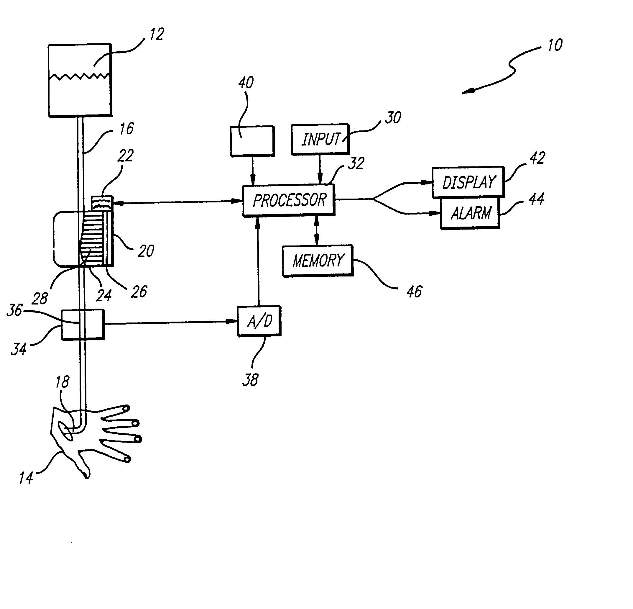
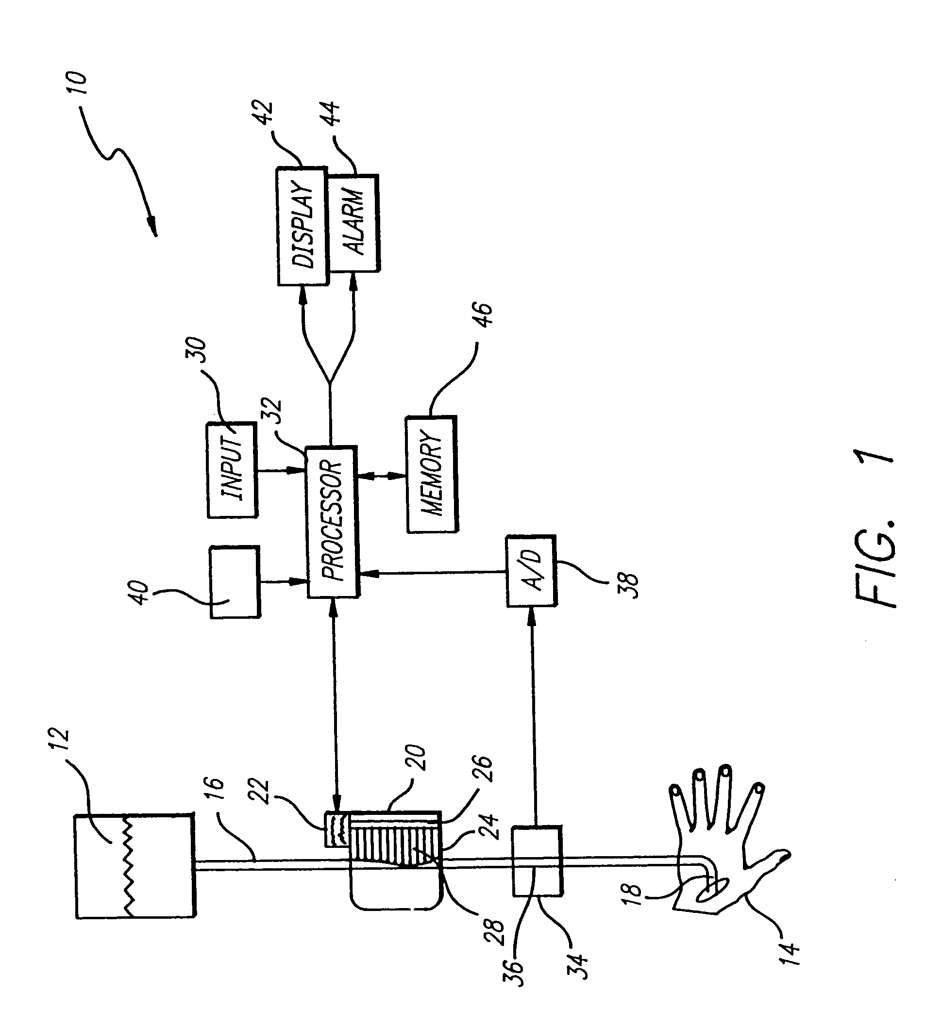
[0037] Referring now to the drawings with more particularity, wherein like reference numerals in the separate views indicate like or corresponding elements, there is shown in FIG. 1 a block diagram of a fluid delivery system 10 incorporating aspects of the current invention. The fluid delivery system includes a fluid source 12 supplying fluid to a patient 14 via a fluid conduit 16 and cannula 18. In the embodiment of FIG. 1, a flow control device 20 controls the flow of fluid through the conduit. The flow control device may include a pump motor 22 driving a pumping mechanism 24, which in the embodiment shown comprises a rotating cam shaft 26 coupled to the pump motor 22 and moving a series of peristaltic elements 28. The peristaltic elements 28 operate on the conduit 16 to move fluid from the fluid source 12, through the conduit 16, and into the patient 14 via the cannula 18.

[0038] In the embodiment of FIG. 1, a user input device 30, such as a keypad, provides operator instructions...


PUM

PropertyMeasurementUnit
timeaaaaaaaaaa
concentrationaaaaaaaaaa
air concentrationaaaaaaaaaa

Abstract

The concentration of air in a fluid delivery line is determined by monitoring output signals corresponding to the amount of air detected in the fluid and processing those signals along with information as to the time or total volume of fluid dispensed since each signal was produced. The processor determines an air concentration value based on the received signal values, with the air concentration value determined by giving greater weight to more recent signal values. Where the air concentration value exceeds a predetermined value, an alarm signal may be activated or fluid delivery may be stopped. The processor also may determine a secondary air concentration value, which may be determined from the raw signal values instead of the weighted signal values. Where the secondary air concentration value exceeds a second predetermined threshold, an alarm signal may be activated or fluid delivery may be stopped.

Description

BACKGROUND OF THE INVENTION [0001] 1. Field of the Invention [0002] The invention relates to fluid delivery systems. More particularly, the present invention relates to detecting air and other agents in a fluid delivery system infusing fluid to a patient. [0003] 2. Description of Related Art [0004] There are a variety of situations where fluid is infused to a patient. Applications of fluid delivery systems include (but are by no means limited to) intravenous infusion, intra-arterial infusion, infusion of enteral solutions, infusion of medication to the epidural space, and diagnostic infusion to determine vascular characteristics of the arterial, urinary, lymphatic, or cerebrospinal systems. [0005] Fluid delivery systems for infusing fluid to a patient typically include a supply of the fluid to be administered, an infusion needle or cannula, an administration set connecting the fluid supply to the cannula, and a flow control device, such as a positive displacement infusion pump. The ...

Claims


Application Information

Patent Timeline
Patent Type & Authority Applications(United States)
IPC IPC(8): A61M5/00A61M5/36G01N29/02G01N29/032G01N29/38
CPCA61M5/365G01N29/032Y10S128/13G01N2291/02433G01N29/38A61M5/14228
Inventor BUTTERFIELD, ROBERT D.FARQUHAR, ALLEN B.
Owner CAREFUSION 303 INC
Why Eureka
Try Eureka