
Hinge device for storage container and storage container having the same

a technology for storage containers and hinges, which is applied in the direction of wing openers, multi-purpose tools, constructions, etc., can solve the problems of increased manufacturing costs, high impact, and difficult assembly process, and achieve the effect of smooth closing and simple configuration

Inactive Publication Date: 2005-09-08
SAMSUNG ELECTRONICS CO LTD
View PDF12 Cites 42 Cited by
  • Summary
  • Abstract
  • Description
  • Claims
  • Application Information

AI Technical Summary

Benefits of technology

[0008] The present invention has been made in view of the above-mentioned problems, and an aspect of the invention is to provide a hinge device for a storage container which includes a pair of hinge couplers combined in the form of a single unit, so that the hinge device has a simple configuration, and enables a door of the storage container to be more smoothly closed, and a storage container, which has the hinge device.
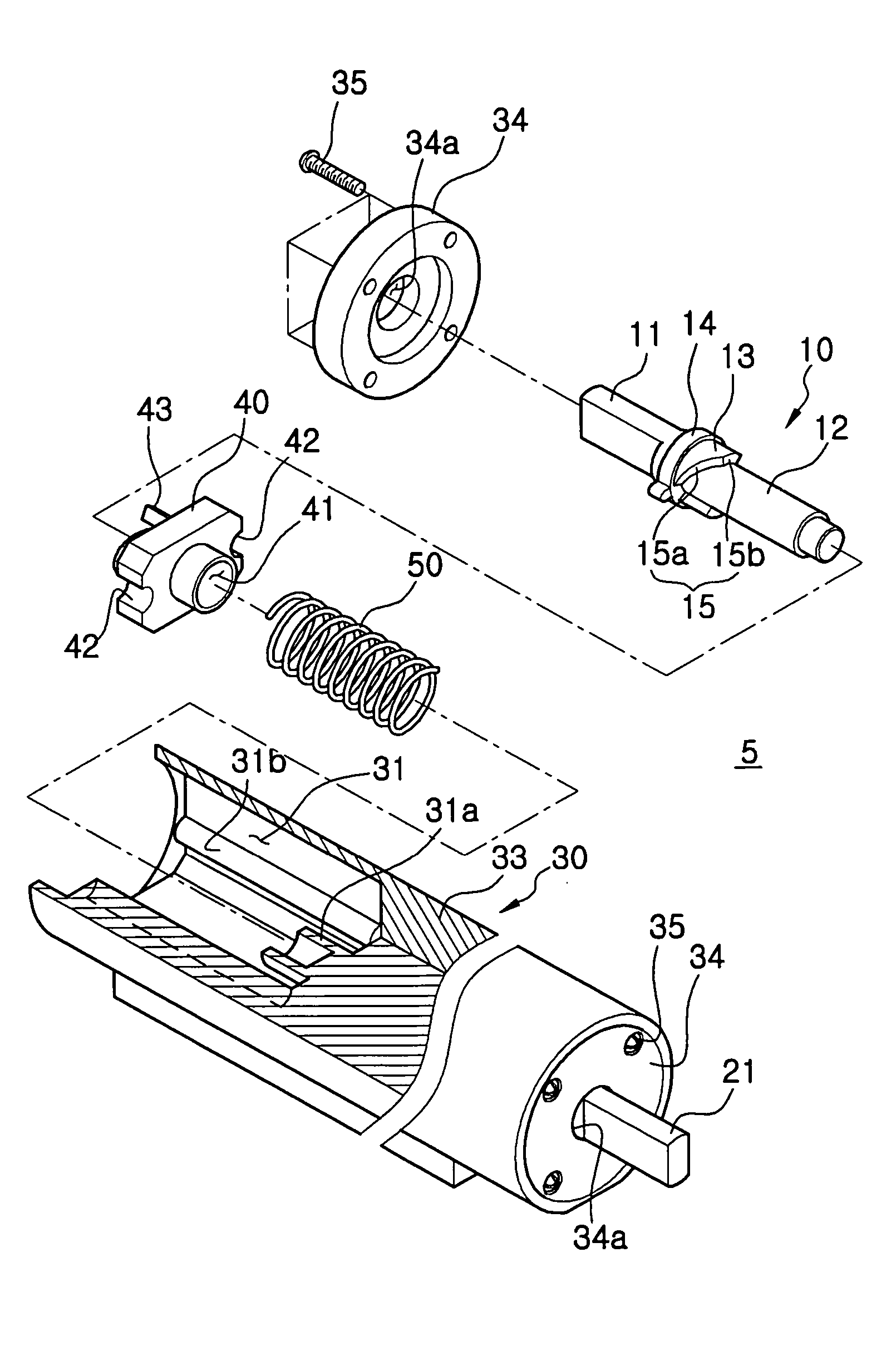
[0009] In accordance with one aspect, the present invention provides a hinge device for a storage container adapted to hingably connect a container body of the storage container and a door of the storage container. The hinge device has a housing fixed to one of the container body and the door, a first hinge shaft and a second hinge shaft rotatably coupled to the housing at opposite sides of the housing, respectively. Each of the first and second hinge shafts have one end extending into the housing, and the other end extending outwardly beyond the housing and fixedly coupled to the other one of the container body and the door. A cam hinge part having a cam shaft section provided at a portion of the first hinge shaft is arranged in the housing to form a first cam. A movable member is formed with a second cam arranged to face the first cam, and an elastic member is provided to press the movable member. Further, a damper is provided at the second hinge shaft to increase a rotational resistance of the door.
[0012] The damper may increase the rotational resistance of the door when the door reaches approximately a position where the door is completely closed.
[0013] The damper may further have a damping boosting portion. The damping booster portion can be provided at a portion of an inner peripheral surface of the damping case at the side of the fluid chamber, which faces the vane when the door reaches approximately a position where the door is completely closed. The damping boosting portion reduces a gap defined between the inner peripheral surface of the damping case and the vane when the door reaches approximately the position where the door is completely closed.
[0021] The insert section may include a first insert section portion arranged in the fluid chamber and provided with an end axially supported by an inner end surface of the damping case opposite to the opening, and a second insert section portion arranged between the extension and the first insert section portion. The damping shaft may further include a first seal portion extending radially outwardly from the second insert section portion at a position adjacent to the first insert section portion, such that the first seal portion comes into contact with the inner peripheral surface of the damping case to prevent the fluid in the fluid chamber from being leaked through the opening.

Problems solved by technology

For this reason, the hinge device involves an increase in manufacturing costs and a difficult assembling process.
Furthermore, there is a problem in that high impact may be generated when the door is closed because the hinge device has an insufficient buffering function in spite of the fact that the door is more or less heavy.

Method used


Image

  • Hinge device for storage container and storage container having the same
  • Hinge device for storage container and storage container having the same
  • Hinge device for storage container and storage container having the same

Examples


Embodiment Construction

[0051] Reference will now be made in detail to illustrative, non-limiting embodiments of the present invention, examples of which are illustrated in the accompanying drawings. The embodiments are described below to explain the present invention by referring to the accompanying figures.

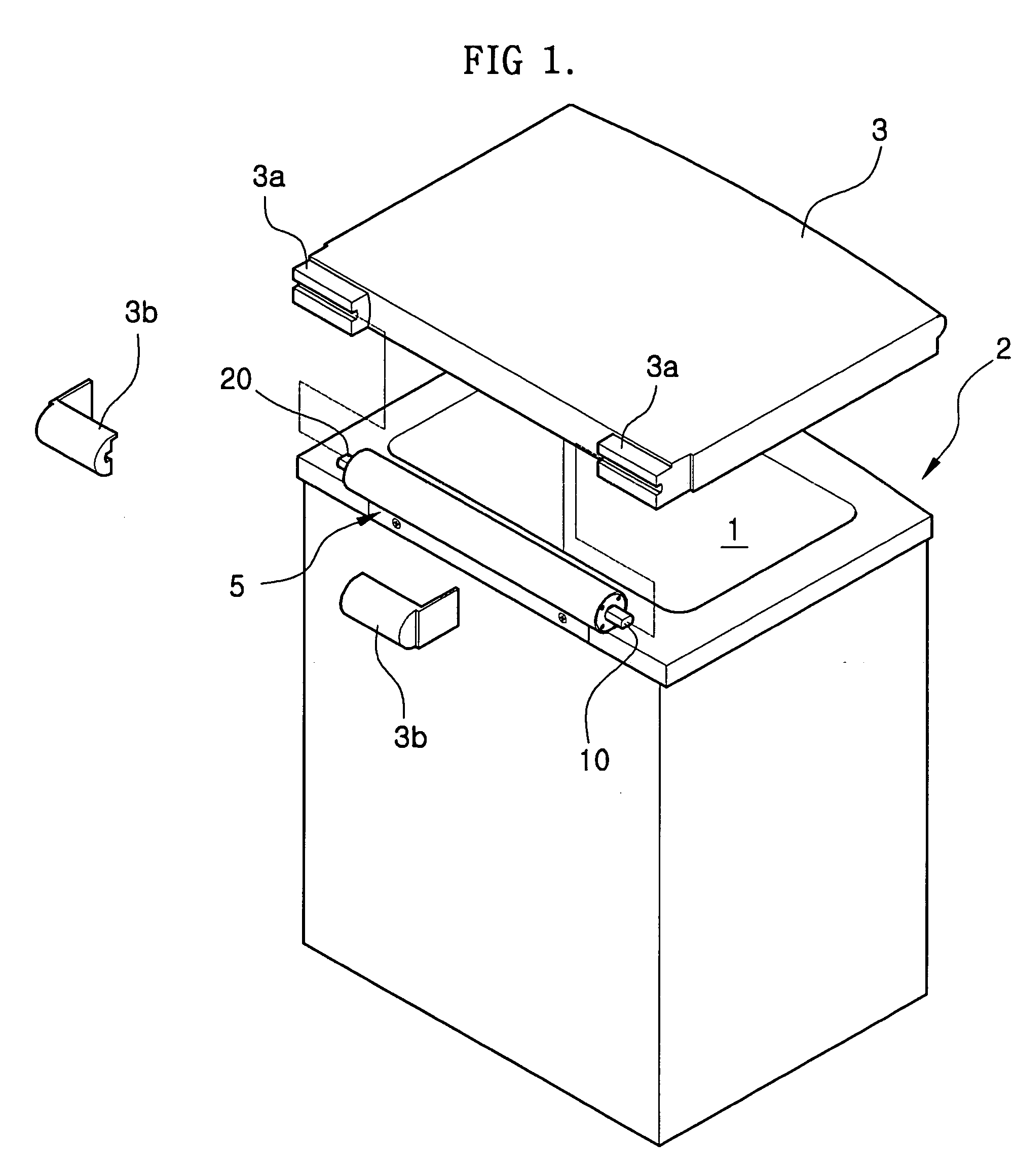
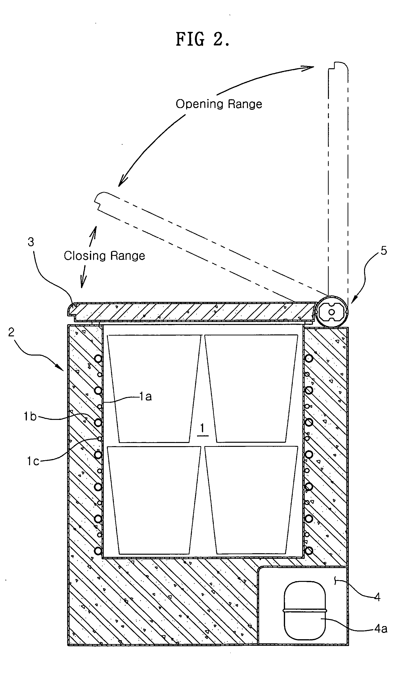
[0052]FIG. 1 is an exploded perspective view illustrating a Kimchi storage container, to which a hinge device consistent with the present invention is applied. FIG. 2 is a sectional view of the Kimchi storage container. As shown in FIGS. 1 and 2, the Kimchi storage container includes a container body 2 made of a thermal insulating material and defined therein with an upwardly-opened storage compartment 1, and a door 3 hingably coupled to the top of the container body 2 to open and close the top of the storage compartment 1.

[0053] An evaporator 1b, which consists of a typical refrigerant tube, is arranged on an outer surface of an inner container wall 1a defining the storage compartment 1, to cool the...


PUM


Abstract

A hinge device for a storage container which includes a pair of hinge couplers combined in the form of a single unit, and enables a door of the storage container to be more smoothly closed without generating impact. A storage container, which includes the hinge device, is also disclosed. The hinge device includes a housing fixed to a container body of the storage container or the door, a first hinge shaft and a second hinge shaft rotatably coupled to the housing at opposite sides of the housing, respectively, each of the first and second hinge shafts having one end extending into the housing, and the other end extending outwardly beyond the housing and fixedly coupled to the other one of the container body and the door, a driver arranged in the housing at the side of the first hinge shaft to apply, to the first hinge shaft, a rotating force to cause the door to be maintained in an opened state or to be closed in accordance with an opening angle of the door, and a damper arranged in the housing at the side of the second hinge shaft to increase a resistance to rotation of the second hinge shaft, and thus, to cause the door to be smoothly closed.

Description

[0001] This application claims priority from Korean Patent Applications No. 2004-15187 and 2004-65961, respectively filed on Mar. 5, 2004 and Aug. 20, 2004 in the Korean Intellectual Property Office, the disclosures of which are incorporated herein by reference. BACKGROUND OF THE INVENTION [0002] 1. Field of the Invention [0003] The present invention relates to a hinge device for a storage container, which hingably couples a door to a body of the storage container, and a storage container, which has the hinge device. More particularly, the present invention relates to a hinge device for a storage container, which hingably couples a door to a body of the storage container, using a simple configuration, and enables the door to be more smoothly closed, and a storage container, which has the hinge device. [0004] 2. Description of the Related Art [0005] In general, as a top opening-type storage container, a typical Kimchi storage container is known, which has an upwardly-opened container...

Claims


Application Information

Patent Timeline
Patent Type & Authority Applications(United States)
IPC IPC(8): E05D11/06E05F3/14E05F3/20E05F5/06
CPCE05D11/06E05F3/14E05F3/20Y10T16/540255E05Y2201/21E05Y2201/256E05Y2201/266E05F5/06E05Y2201/254E05Y2201/264E05F5/10E05Y2201/638E05F1/1223
Inventor NAM, JEONG MANKIM, JI MANKIM, YONG MYOUNG
Owner SAMSUNG ELECTRONICS CO LTD
Learn More