Multi-stage no-oil gas compressor

a gas compressor and multi-stage technology, applied in the field of gas compressors, can solve the problems of high rotational speed, difficult to achieve, and the effect of reducing the number of oil cylinders

Inactive Publication Date: 2005-09-08
CORAC GROUP
View PDF11 Cites 11 Cited by
  • Summary
  • Abstract
  • Description
  • Claims
  • Application Information

AI Technical Summary

Benefits of technology

[0013] The invention combines the benefits of each type of no oil compressor configuration into one unit, exploiting the potential compactness of a high speed electrically driven rotodynamic compressor first stage with a screw compressor element second stage, as has been previously disclosed. The high speed rotodynamic stage can provide a high volumetric flow in a relatively compact arrangement, thus making it suitable for the inlet stage, whereas the screw stage has the ability to accommodate variable inlet conditions with it remaining able to achieve constant pressure delivery. In a comparable two stage screw machine, the inlet stage is large and bulky and its substitution with a high speed rotodynamic unit offers cost as well as performance benefits.
[0014] This invention proposes to utilize water to cool the gas directly via a spray cooler system. In this instance, water is injected via spray nozzles into the gas stream exiting the first centrifugal stage compressor. By using this approach, high thermal exchange rates can be achieved with negligible pressure drop, as the gas is in intimate contact with the water. The absence of plates and tubes in the intercooling stage eliminates any thermal resistance from this part of the process. It also reduces cost, complexity and size.
[0015] The main significance of this arrangement is that the subsequent screw stage can accept a gas / water mixture, which can result in a further compression efficiency improvement. By adopting this approach, a proportion of the water is effectively introduced into the screw at inlet. While in a water-flooded screw compressor, the whole of the water can be introduced in this manner, in the preferred embodiment of the invention the proportion is about one half and the remainder is injected at some intermediate point in the compression process within the screw. This is preferred because it has the effect of introducing the liquid when it is needed rather than all at one position.
[0019] The presence of water in the water lubricated screw stage obviates the need for an aftercooler. The gas exiting the screw stage is nominally at 50° C. and a simple centrifugal separator and refrigerant drier ensures that all the water can be recovered and the delivered gas is free of contaminants and particularly oil free.

Problems solved by technology

To increase the outlet pressure, higher rotational speeds are required which can become difficult to achieve while maintaining an acceptable efficiency relative to other approaches.
To remove any oil effectively from the air requires significant investment and maintenance of filtering systems.
The conventional heat exchangers exhibit a pressure drop in the system unless they are substantially oversized, whereupon they become prohibitively expensive.
They therefore present a source of poor efficiency and are a substantial component of the overall cost of the machine.
In the case of screw compressors, because of the nature and complexity of the screw profile, the size of the compressor is limited by the machining accuracy achievable that ensures low leakage and high compression efficiencies.
This makes screw compressors less suitable for high volume flows.
Difficulties occur at small volumes where smaller machines are required that run at increasingly higher rotational velocities to ensure adequate momentum exchange.
This presents balancing and bearing related problems as balancing accuracies need to be increased and speeds can be in excess of conventional bearing capabilities.

Method used


Image

  • Multi-stage no-oil gas compressor
  • Multi-stage no-oil gas compressor

Examples


Embodiment Construction

[0023] It should be understood that these embodiments are only examples of the many advantageous uses of the innovative teachings herein. In general, statements made in the specification of the present application do not necessarily limit any of the various claimed inventions. Moreover, some statements may apply to some inventive features but not to others. In general, unless otherwise indicated, singular elements may be in the plural and vice versa with no loss of generality.

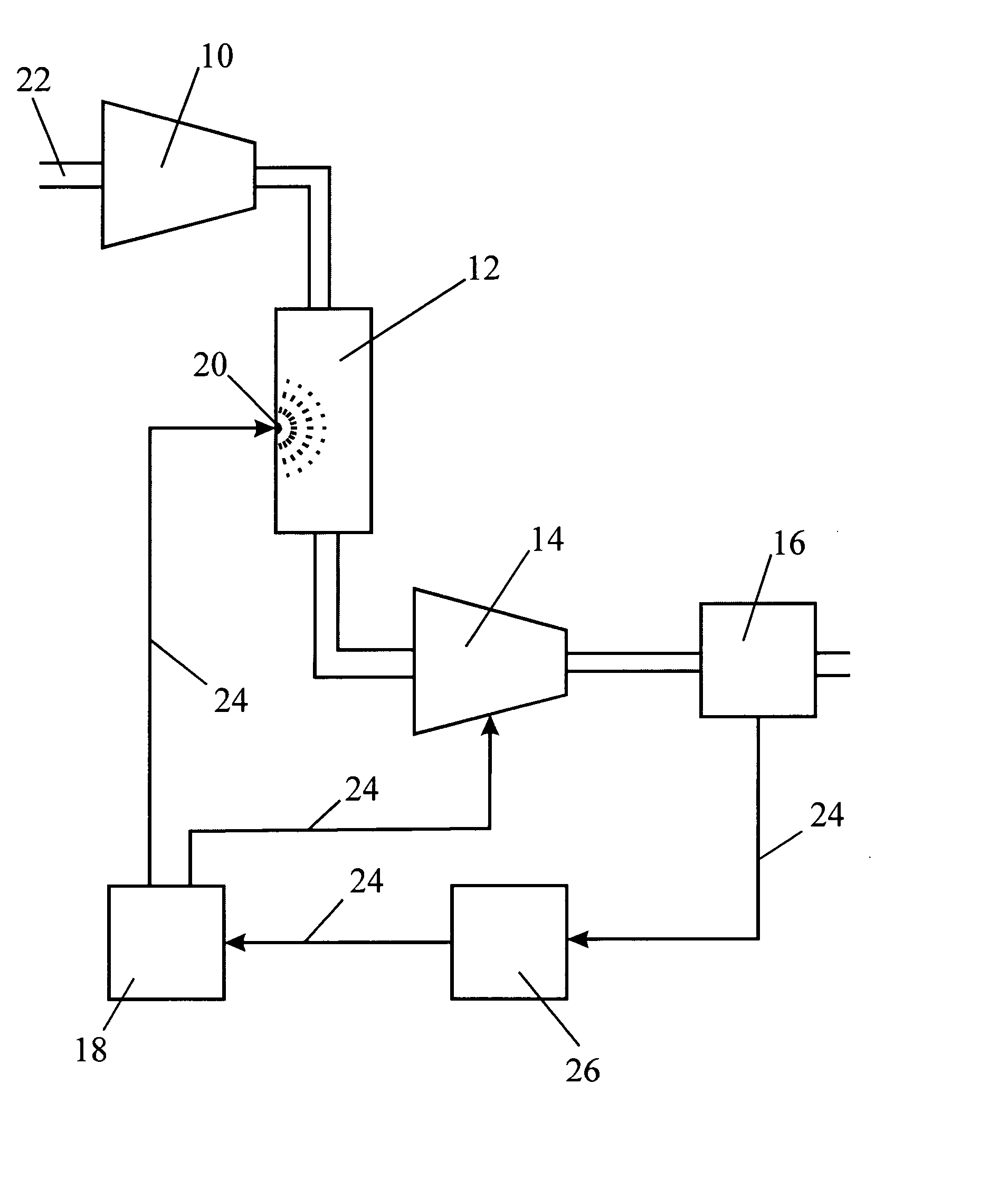
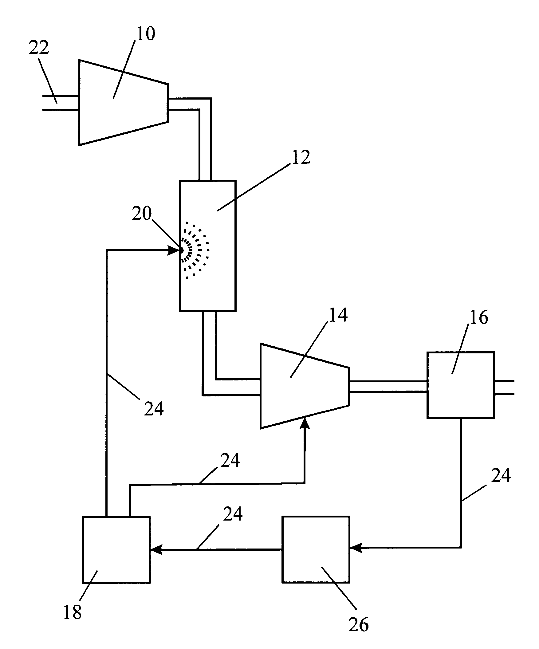
[0024] In the single figure, the conduits along which gas flows are represented by double lines whereas the pipes, numbered 24, that carry water are shown as single lines.

[0025] Gas to be compressed enters at 22 into an electrically driven centrifugal compressor 10. Once compressed by the centrifugal compressor 10, the hot gas flows through a water spray intercooler 12.

[0026] The water spray intercooler 12 is effectively a canister which slows down the gas. At the same time, water is injected at high pressur...


PUM

PropertyMeasurementUnit
temperatureaaaaaaaaaa
speedaaaaaaaaaa
sizeaaaaaaaaaa

Abstract

A multi-stage compressor comprises a variable speed electrically driven rotodynamic compressor stage connected in series with and upstream of a water lubricated screw compressor stage and an intercooler arranged between the two compressors to reduce the temperature of gas entering the screw compressor stage. In the invention, the intercooler is a water spray intercooler, the water supply of which is shared with that of the water lubricated screw compressor.

Description

CROSS-REFERENCE TO RELATED APPLICATIONS [0001] This application is based upon and claims priority from prior Great Britain Patent Application No. 0404948.2, filed on Mar. 5, 2004 which is based on Great Britain Patent Application No. 0425734.1 filed on Nov. 23, 2004, each of which is hereby incorporated by reference in its entirety. FIELD OF THE INVENTION [0002] The present invention generally relates to gas compressors and more practically to a multi-stage no-oil gas compressor with an intercooling arrangement. BACKGROUND OF THE INVENTION [0003] There are many techniques available to compress gases and each has its merits in terms of the total pressure rise, the volume flow rate that can be achieved and the efficiency at which the process can operate. [0004] A rotodynamic compressor, which term includes axial flow compressors and centrifugal compressors, achieves gas compression by using a high speed rotor to increase the momentum of the gas, the momentum being converted to a press...

Claims


Application Information

Patent Timeline
Patent Type & Authority Applications(United States)
IPC IPC(8): F04B41/06
CPCF04B41/06
Inventor ALFORD, ADRIANCROMM, GERD WILHELMREED, JULIAN OLIVER
Owner CORAC GROUP
Why Eureka
Try Eureka