
Method for separating analyte from a sample

a technology of analyte and sample, applied in the field of method for separating analyte from a sample, can solve the problems of complex fluidic assembly processing algorithms, limited volume of fluid sample which can be processed, and complex contemporary biomedical processing instruments. , to achieve the effect of superior blend of efficiency and convenience in design, manufacture and us

Inactive Publication Date: 2005-09-08
CEPHEID INC
View PDF99 Cites 124 Cited by
  • Summary
  • Abstract
  • Description
  • Claims
  • Application Information

AI Technical Summary

Benefits of technology

The present invention is a device and method for separating and concentrating desired analytes from fluid samples. It combines the benefits of microfluidic chips and larger cartridges in a single device, making it more efficient and convenient than traditional lab-on-a-chip technology. The device includes a cartridge with a sample flow path and a capture region for capturing the desired analyte. The captured analyte is then released into an elution fluid in a separate elution flow path. The device also includes a lysing region for lysing cells or other microorganisms in the sample. The invention allows for the rapid processing of larger sample volumes and increased sensitivity in detecting low copy concentrations of analytes. The device can be used with various external instruments for receiving and manipulating the samples.

Problems solved by technology

Whether incorporated into a bench-top instrument, a disposable cartridge, or a combination of the two, such processing involves complex fluidic assemblies and processing algorithms.
Contemporary biomedical processing instruments are typically complex, robotically operated devices that move boluses of liquids automatically from one processing region to another.
While the bolus approach allows for the implementation of complex processing methods, the volume of the fluid sample which can be processed is limited by the size of the individual processing regions, especially where the sample is transiently processed.
Thus, the lowest detectable concentration of analyte, i.e. sensitivity, in any assay based on a bolus approach is also limited.
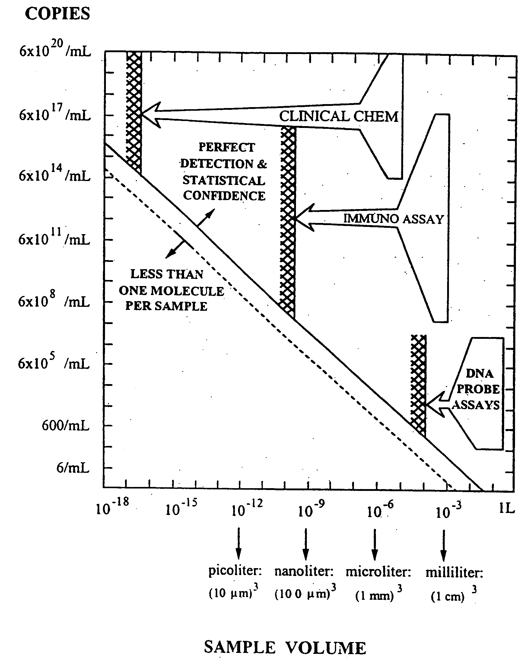
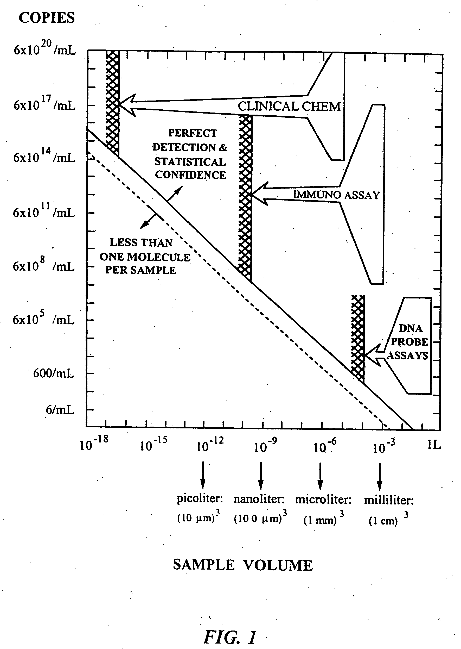
Such a large chip would not only be expensive, but would also defeat the purpose of miniaturization, especially for many types of disposable medical or environmental diagnostic uses.
These small volumes are not practical for many realistic diagnostic applications.

Method used


Image

  • Method for separating analyte from a sample
  • Method for separating analyte from a sample
  • Method for separating analyte from a sample

Examples


Embodiment Construction

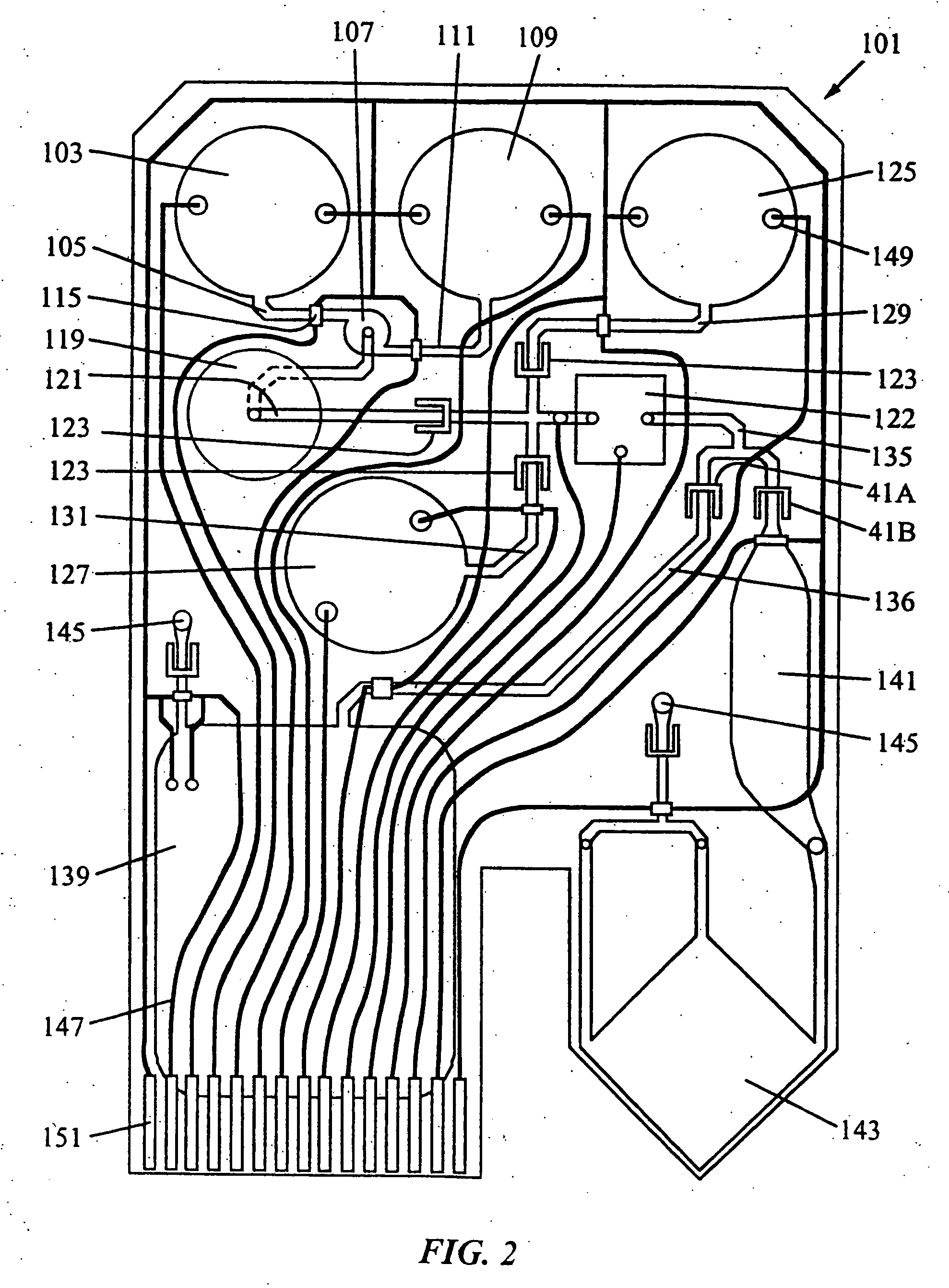
[0042] The present invention provides a cartridge for performing various operations on a fluid sample as the sample flows through a series of interconnected, interactive regions within the cartridge. The regions are located sequentially along a fluid flow path through the cartridge, so that a segment of the fluid stream is exposed to a specific operation at one region, then another operation at the next region, etc. The sample flows through the interactive regions so that it is simultaneously in contact with more than one region at a given time. The sample flow is preferably continuous, so that the operations at each region occur simultaneously and sequentially on the fluid stream.

[0043] The cartridges of the present invention allow for significantly improved processing of a fluid sample for the detection and / or analysis of chemical components in the sample, such as biological molecules. A pioneering improvement over the prior art is the ability to rapidly process a fluid sample th...


PUM

PropertyMeasurementUnit
volumeaaaaaaaaaa
flow rateaaaaaaaaaa
ionic strengthaaaaaaaaaa

Abstract

An analyte is separated from a fluid sample by introducing the sample into a cartridge having a sample port and a first flow path extending from the sample port. The first flow path includes an extraction chamber containing a solid support for capturing the analyte from the sample. The cartridge has a second flow path for eluting the captured analyte from the extraction chamber, the second flow diverging from the first flow path after passing through the extraction chamber. The sample is forced to flow through the extraction chamber and into a waste chamber, thereby capturing the analyte with the solid support as the sample flows through the extraction chamber. The captured analyte is then eluted from the extraction chamber by forcing an elution fluid to flow through the extraction chamber and along the second flow path.

Description

PARENT APPLICATION DATA [0001] This application is a division of co-pending U.S. application Ser. No. 09 / 331,911 filed Jun. 25, 1999 as a national stage entry (371) of International Application PCT / US98 / 27632 filed Dec. 24, 1998 which international application claims priority from U.S. application Ser. No. 09 / 115,454 filed Jul. 14, 1998, now abandoned. All of these applications are incorporated by reference herein for all purposes.FIELD OF THE INVENTION [0002] This invention relates to a method for separating an analyte from a sample. BACKGROUND OF THE INVENTION [0003] The analysis of clinical or environmental fluids generally involves a series of chemical, optical, electrical, mechanical, or thermal processing steps on the fluid samples. Whether incorporated into a bench-top instrument, a disposable cartridge, or a combination of the two, such processing involves complex fluidic assemblies and processing algorithms. [0004] Contemporary biomedical processing instruments are typicall...

Claims


Application Information

Patent Timeline
Patent Type & Authority Applications(United States)
IPC IPC(8): G01N31/20B01D11/00B01J19/00B01L3/00B01L7/00C12M1/00C12M1/26C12M1/33C12M1/34C40B60/14G01N1/28G01N30/60G01N33/50G01N35/08G01N37/00
CPCB01J2219/00432Y10T436/25375B01L3/502715B01L3/502753B01L7/52B01L2200/0621B01L2200/0631B01L2200/0636B01L2200/10B01L2300/0816B01L2300/1827B01L2400/0421B01L2400/046B01L2400/0487B01L2400/0622B01L2400/0644B01L2400/086C40B60/14G01N30/6091G01N30/6095C12M47/06Y10T436/255B01J2219/00529B01L2300/0883G01F1/708C12M47/02
Inventor POURAHMADI, FARZADMCMILLAN, WILLIAM A.CHING, JESUSCHANG, RONALDCHRISTEL, LEE A.KOVACS, GREGORY T.A.NORTHRUP, M. ALLENPETERSEN, KURT E.
Owner CEPHEID INC
Learn More