Electrostatic atomizer for a painting robot

a technology of atomizer and painting robot, which is applied in the direction of electrostatic spraying apparatus, burners, spraying power supplies, etc., can solve the problems of kinks of low voltage cables and breakage of wires in low voltage cables, excessive tensile force or other kinds of force, and invited breakage or disconnection of connectors

Inactive Publication Date: 2005-09-08
RANSBURG IND FINISHING
View PDF7 Cites 12 Cited by
  • Summary
  • Abstract
  • Description
  • Claims
  • Application Information

AI Technical Summary

Benefits of technology

[0007] It is therefore an object of the invention is to provide an electrostatic atomizer for a painting robot, which can prevent breakage of a power supply cable extending through a wrist portion of a robot arm even under rotations of the wrist portion.

Problems solved by technology

Such movements of the wrist portions, however, often caused kinks of the low voltage cables and breakage of the wires in the low voltage cables.
Furthermore, since existing electrostatic atomizers contained high-voltage generators inside and electric power was supplied through low-voltage cables inside the robot arms, torsions produced in the low-voltage cables by the rotations of the arm wrist portions often caused excessive tensile force or other kinds of force to the connectors of the high-voltage generators inside the electrostatic atomizers, and often invited breakage or disconnection of the connectors.

Method used


Image

  • Electrostatic atomizer for a painting robot
  • Electrostatic atomizer for a painting robot
  • Electrostatic atomizer for a painting robot

Examples


first embodiment (fig.1)

First Embodiment (FIG. 1)

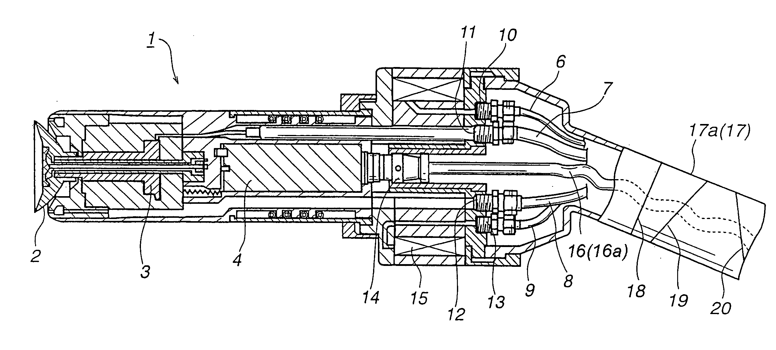
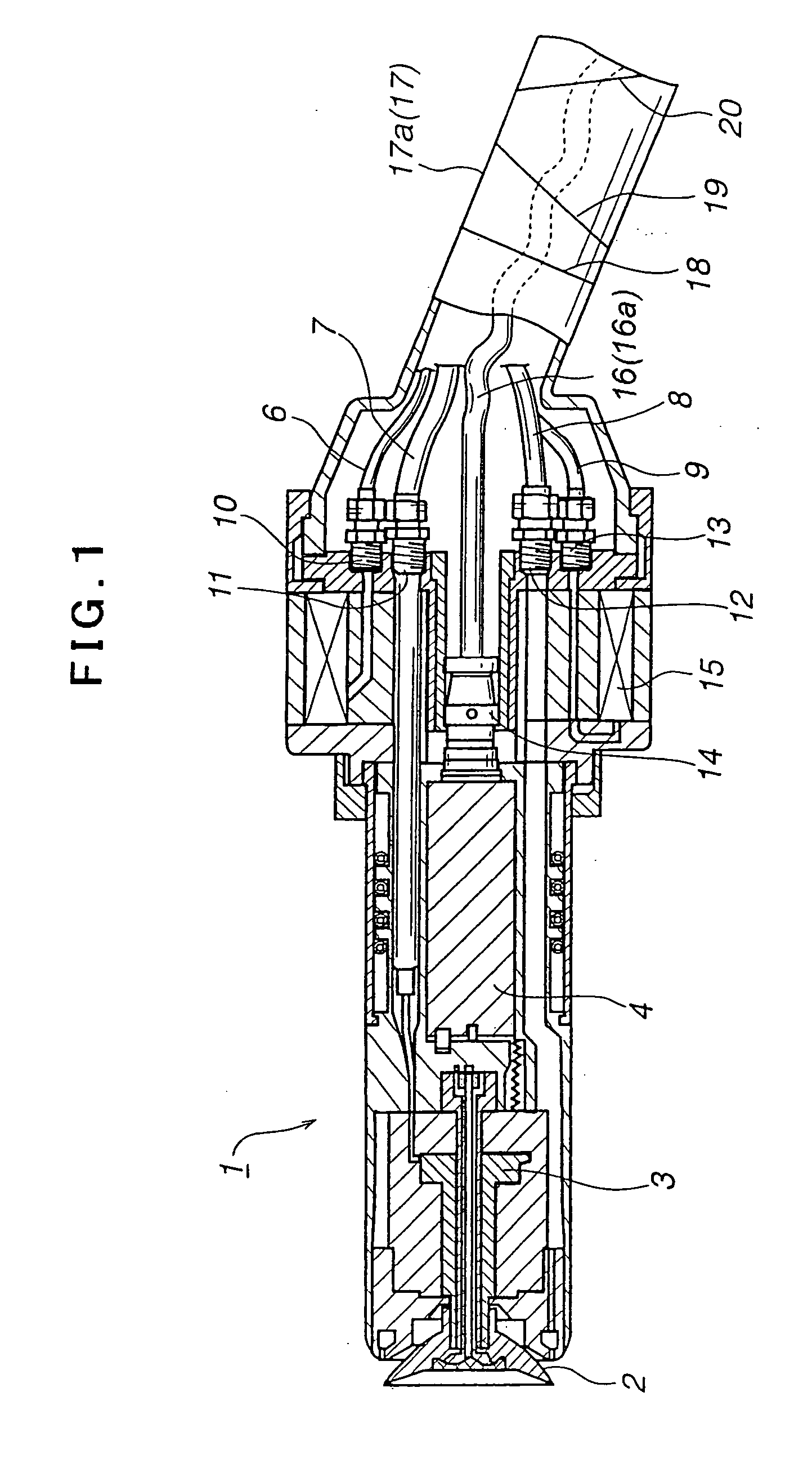
[0021]FIG. 1 shows an electrostatic atomizer 1 according to the first embodiment of the invention. The electrostatic atomizer 1 shown here is of a rotary atomization type. Like the conventional electrostatic atomizers, this atomizer 1 includes therein an air motor 3 for driving the rotary atomizer head 2 to rotate at a high speed, high voltage generator 4 of a cascade type, and valve mechanism 5. The rear end surface 1a of the electrostatic atomizer 1 has formed ports 10 through 13 to which air and paint pipes 6 through 9 are connected.

[0022] A connector 14 on the rear end surface of the high voltage generator 4 is fixed inside a sleeve 15, and the low voltage cable 16 is connected to the high voltage generator 4 via the connector 14. The low voltage cable 16, however, may be connected to the high voltage generator without the connector 14.

[0023] The electrostatic atomizer 1 is attached to the distal end of an arm 17 of a painting robot (not shown). Simila...

second embodiment (fig.2)

Second Embodiment (FIG. 2)

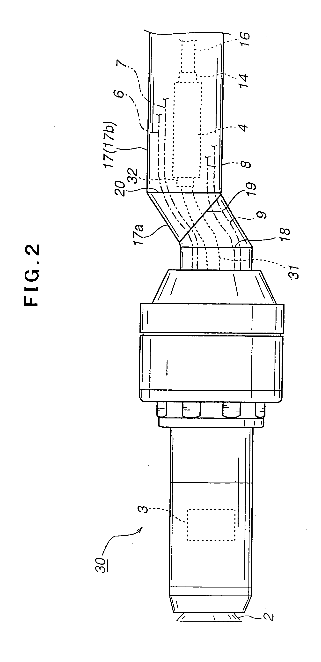
[0026] Next explained is an electrostatic atomizer 30 for a painting robot according to the second embodiment of the invention with reference to FIG. 2. In FIG. 2, identical or equivalent parts and components to those of the atomizer 1 according to the first embodiment are labeled with common reference numerals, and their explanation is omitted in the following description. Therefore, the following explanation of the second embodiment is limited to the features different from the first embodiment.

[0027] Unlike the first embodiment locating the high voltage generator 4 inside the atomizer, the electrostatic atomizer 30 according to the second embodiment locates the high voltage generator 4 inside the arm main body 17b of the robot arm 17. Thus, the electrostatic atomizer 30 according to the second embodiment is supplied with high voltage generated in the high voltage generator 4 via a high voltage cable 31. Reference numeral 32 denotes a connector.

[0028] T...


PUM


Abstract

An electrostatic atomizer (1) is attached to the distal end of an arm (17) of a painting robot to change the direction of paint sprayed from it, following to movements of a wrist portion (17a) of the arm (17). The electrostatic atomizer 1 includes a high voltage generator (4) that is supplied with electric power via a low voltage cable (16) extending through the arm (17). The low voltage cable (16) has an elastically shaped portion (16a) at least as a part thereof. The elastically shaped portion (16a) absorbs torsional or tensile force produced in the low voltage cable (16) under rotations of the wrist portion (17a) of the arm (17) and thereby prevents breakage of wires in the low voltage cable (16).

Description

FIELD OF THE INVENTION [0001] The present invention relates to an electrostatic atomizer to be attached to the distal end of an arm of a painting robot. BACKGROUND OF THE INVENTION [0002] Painting or coating robots are widely used for coating vehicle bodies, for example. Coating robots have arms. Wrist portions of the arms are rotatable about a plurality of axes to change orientation of atomizers attached to distal ends of the wrists and to change the direction of sprays of coating materials from the atomizers. Therefore, coating robots have been used for coating surfaces having complicated topographies, such as inner surfaces of vehicle bodies. [0003] Japanese Patent Laid-open Publication No. 8-164349 discloses a typical electrostatic atomizer for a painting robot. In electrostatic atomizers of this type, paint and compressed air are supplied to the atomizer through a pipe passing through the robot arm together with a power supply cable, through which the atomizer is electrically p...

Claims


Application Information

Patent Timeline
Patent Type & Authority Applications(United States)
IPC IPC(8): B05B5/025B05B5/04B05B5/053B05B13/02B05B13/04B25J19/00
CPCB05B5/0407B05B5/053B25J19/0029B05B13/0431B05B13/0278
Inventor SAKAKIBARA, MASAHITOSAITOU, HIDEKINAGAI, KIMIYOSHI
Owner RANSBURG IND FINISHING
Why Eureka
Try Eureka