Axial gap rotating electrical machine

a rotating electrical machine and axial gap technology, applied in the direction of dynamo-electric machines, dynamo-electric components, magnetic circuit shapes/forms/construction, etc., can solve the problems of uneven magnetic path at the outer periphery and inner periphery, insufficient magnetic force of permanent magnets in the torque, and too large magnetic flux density on the inner circumferential side, so as to prevent magnetic saturation of the core. , the effect of improving the torque outpu

Active Publication Date: 2005-09-08
EQUOS RES
View PDF3 Cites 73 Cited by
  • Summary
  • Abstract
  • Description
  • Claims
  • Application Information

AI Technical Summary

Benefits of technology

[0019] According to the axial gap rotating electrical machine of the present invention, the amount of magnetic flux on the outside in the radial direction of the rotor is set to be larger than the amount of magnetic flux on the inside in the radial direction of the rotor,

Problems solved by technology

As a result, the width of the magnetic path becomes narrower on the inner circumferential side of the rotor than it is on the outer circumferential side, so that the magnetic path at the outer periphery and magnetic path at the inner periphery are uneven.
When a component in the radial direction of the rotor is generated in the magnetic flux vector, that component does not contribute to the driving force which rotates the rotor, so the magnetic force of the permanent magnets cannot be sufficiently reflected in the torque.
Furthermore, with a structure in which the magnetization surfaces of the perma

Method used


Image

  • Axial gap rotating electrical machine
  • Axial gap rotating electrical machine
  • Axial gap rotating electrical machine

Examples


first embodiment

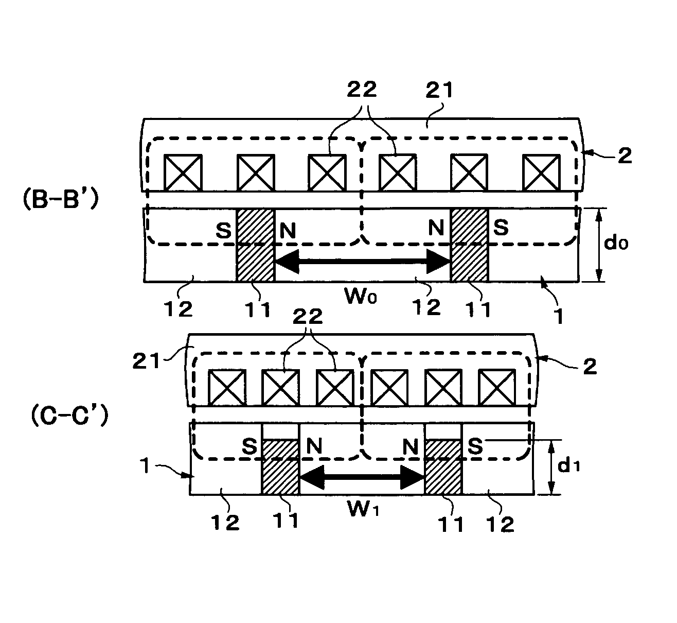
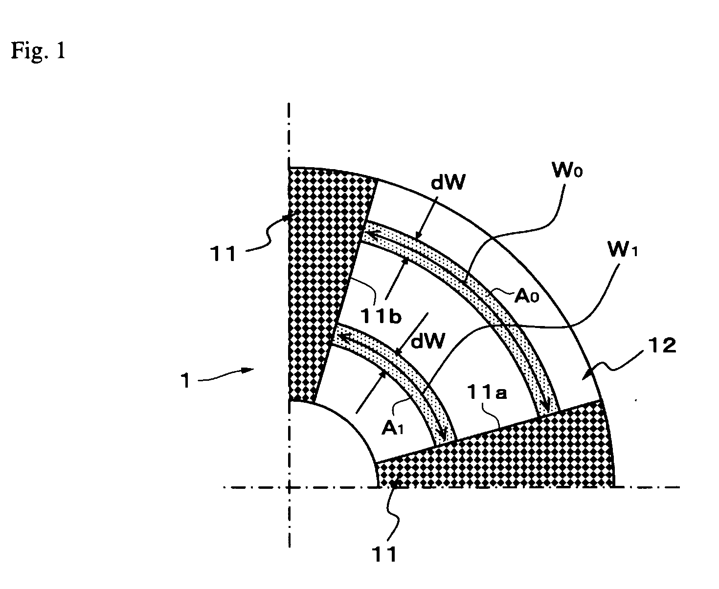
[0045] Exemplary embodiments of the present invention will hereinafter be described with reference to the appended drawings. FIGS. 2 to 4 show a first exemplary embodiment. This exemplary embodiment realizes a structure in which the amount of magnetic flux on the outside in the radial direction of a rotor 1 is made greater than the amount of magnetic flux on the inside in the radial direction by making the sectional area (S) per unit length (i.e., the dW), in the radial direction of the rotor, of permanent magnets (hereinafter simply referred to as “magnets” in the embodiments) 11 larger at the outer circumferential side than it is at the inner circumferential side. More specifically, the magnets 11 in this exemplary embodiment are made thinner, when viewed in the axial direction of the rotor 1 (i.e., the direction perpendicular to the paper on which the drawing is drawn), on the inner radial side of the rotor than they are on the outer radial side of the rotor.

[0046]FIG. 2 is a re...

second embodiment

[0060] Next, a second exemplary embodiment shown with reference to FIGS. 8 and 9 realizes a structure in which the amount of magnetic flux on the outside in the radial direction of the rotor 1 is made larger than the amount of magnetic flux on the inside in the radial direction by making a magnetomotive force (F) in each position, in the radial direction of the rotor, of the magnets 11 greater at the outer circumferential side of the rotor than it is at the inner circumferential side of the rotor. More specifically, the magnets 11 in this example are structured so that their widths, when viewed from the circumferential direction of the rotor 1, are made smaller on the inner radial side of the rotor than they are on the outer radial side of the rotor.

[0061]FIG. 8 is a representational plan view of the rotor as viewed from the side that faces the stator. FIG. 9 is a representational sectional view of cross-sections taken across lines D-D′ and E-E′ of FIG. 8. All of the basic structur...

third embodiment

[0069] Next, a third exemplary embodiment shown with reference to FIG. 10 realizes a structure in which the amount of magnetic flux at the outside in the radial direction of the rotor 1 is made larger than the amount of magnetic flux at the inside in the radial direction of the rotor 1 by making the magnetic flux density (B), in the radial direction of the rotor, at the magnetization surfaces of the magnets greater on the outer radial side than it is on the inner radial side. More specifically, the magnets 11 in this example are structured such that the amount of magnetization in the radial direction of the rotor is less on the inner radial side than it is on the outer radial side.

[0070]FIG. 10 is a representational sectional view showing the rotating electrical machine cut at the same portions as the cross-sections taken along lines B-B′ and C-C′ in the representational plan view (FIG. 2) of the first exemplary embodiment (in this example, the cross-sections are denoted by F-F′ an...


PUM


Abstract

An axial gap rotating electrical machine is provided with permanent magnets and cores in a rotor. The permanent magnets are oriented such that magnetization surfaces face in the circumferential direction of the rotor. The cores are arranged alternately with the permanent magnets in the circumferential direction of the rotor. The amount of magnetic flux on the outside in the radial direction of the rotor is made greater than the amount of magnetic flux on the inside in the radial direction of the rotor. As a result, the magnetic flux density at the rotor cores can be made substantially constant in the radial direction of the rotor and torque output with respect to the size of the permanent magnets is improved by preventing magnetic saturation of the cores.

Description

BACKGROUND OF THE INVENTION [0001] 1. Field of the Invention [0002] The present invention relates to a rotating electrical machine such as a motor or a generator. More particularly, the present invention relates to an axial gap rotating electrical machine in which a disc-shaped rotor and a stator are oriented opposing one another in the axial direction. [0003] 2. Description of the Related Art [0004] A so-called axial gap motor is known in which a stator is arranged opposing end surfaces, in the axial direction, of a disc-shaped rotor across an air gap. This motor obtains rotational driving force from magnetic force acting between the surfaces of the axially opposing rotor and stator. The axial gap motor is advantageous in that it can be made thinner in the axial direction than a so-called radial type motor which has a conventional cylindrical rotor and an annular stator that surrounds the peripheral surface of the rotor. [0005] Presently several types of rotors for axial gap motors...

Claims


Application Information

Patent Timeline
IPC IPC(8): H02K1/22H02K1/27H02K7/09H02K21/12
CPCH02K1/2793H02K21/24H02K1/2796
Inventor HASEBE, MASAHIROISHIKAWA, MASAMIMIZUNO, AKIRA
Owner EQUOS RES
Why Eureka
Try Eureka