Liquid crystal display and liquid crystal display driving method

a technology of liquid crystal display and driving method, which is applied in the direction of digital storage, instruments, optics, etc., can solve the problems of uneven gray scale display and overcharge, and achieve the effect of improving resolution and response speed of liquid crystal display and preventing uneven gray scale display

Inactive Publication Date: 2005-09-08
SHARP KK
View PDF18 Cites 29 Cited by
  • Summary
  • Abstract
  • Description
  • Claims
  • Application Information

AI Technical Summary

Benefits of technology

[0011] It is an object of the invention to provide a liquid crystal display that can carry out “gate-jumping two pulse driving,” which is effective in preventing uneven gray scale display caused by overcharge in pre-charging, and in improving a resolution and response speed of the liquid crystal display.
[0013] As mentioned above, in a driving method in which actual charging for a current line and pre-charging for a subsequent line (any line following the actually charged line) are carried out during one horizontal period, a pixel is charged twice by pre-charging and actual charging. Though the driving method is effective in improving a resolution and response speed of the liquid crystal display in TFT liquid crystal driving, it can cause uneven gray scale display by the overcharge due to pre-charging.
[0014] To solve the problem, in the structure mentioned above, data respectively applied to the actually charged line and the pre-charged line which are charged in the same horizontal period are compared (a charge level of pre-charging and a charge level of actual charging are compared with respect to the same pixel), and a pre-charge period of the pre-charged line is adjusted based on the result of comparison. To be precise, the adjustment of a pre-charge period reduces the pre-charge period and thereby avoid overcharge in pixels which are likely to be overcharged by pre-charging. This effectively improves a resolution and response speed of the liquid crystal display while preventing uneven gray scale display caused by overcharge due to pre-charging.
[0016] With the structure mentioned above, the charge period is controlled by using different gate clock signals for the actually charge line and pre-charged line of the same horizontal period. Thus, the amount of charge for the actually charged pixel and pre-charged pixel connected to the same source line can be independently controlled without increasing the number of source lines. This is effective in improving a resolution and response speed of the liquid crystal display while preventing uneven gray scale display caused by overcharge due to pre-charging.

Problems solved by technology

Though the driving method is effective in improving a resolution and response speed of the liquid crystal display in TFT liquid crystal driving, it can cause uneven gray scale display by the overcharge due to pre-charging.

Method used


Image

  • Liquid crystal display and liquid crystal display driving method
  • Liquid crystal display and liquid crystal display driving method
  • Liquid crystal display and liquid crystal display driving method

Examples


Embodiment Construction

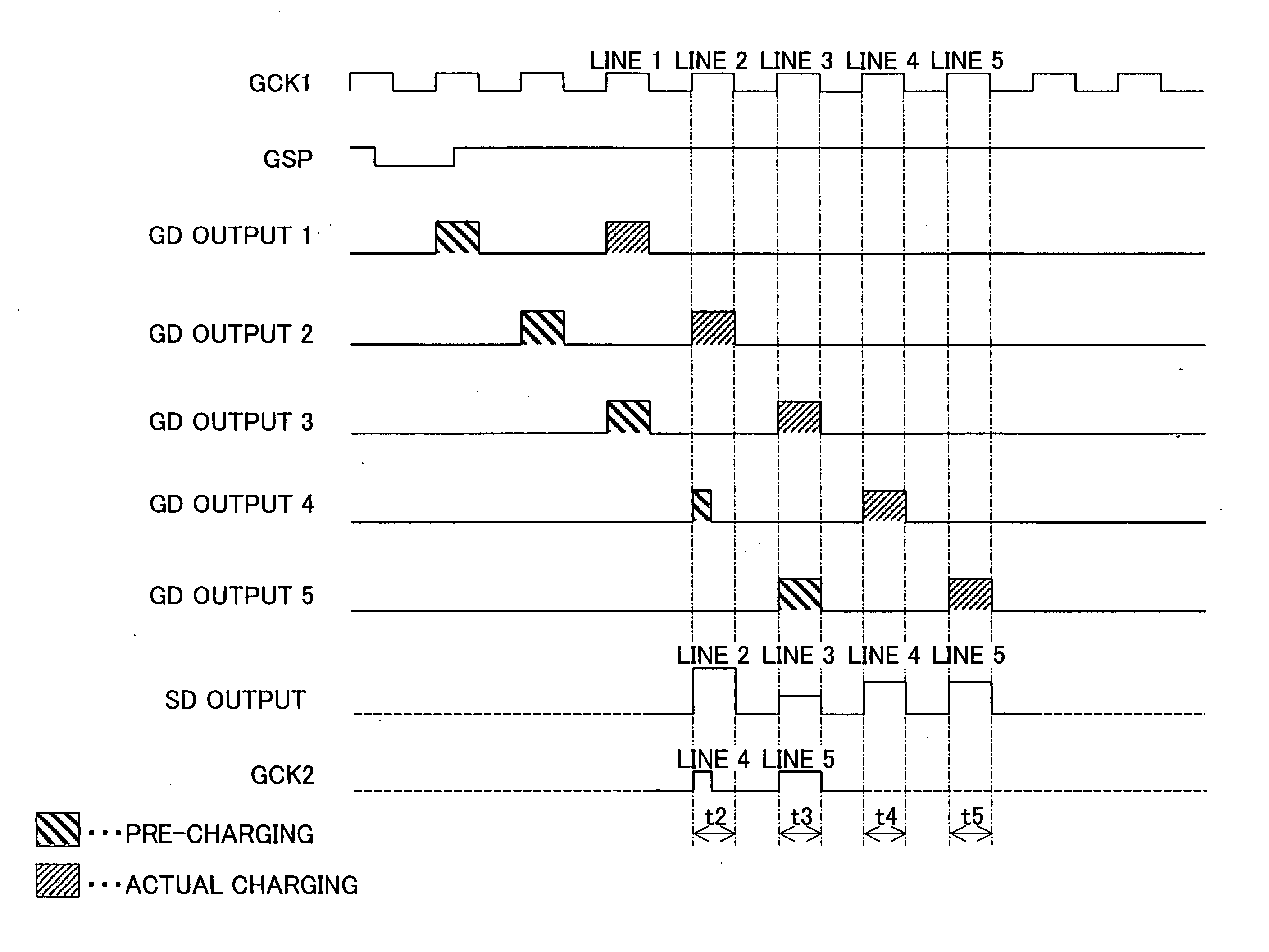
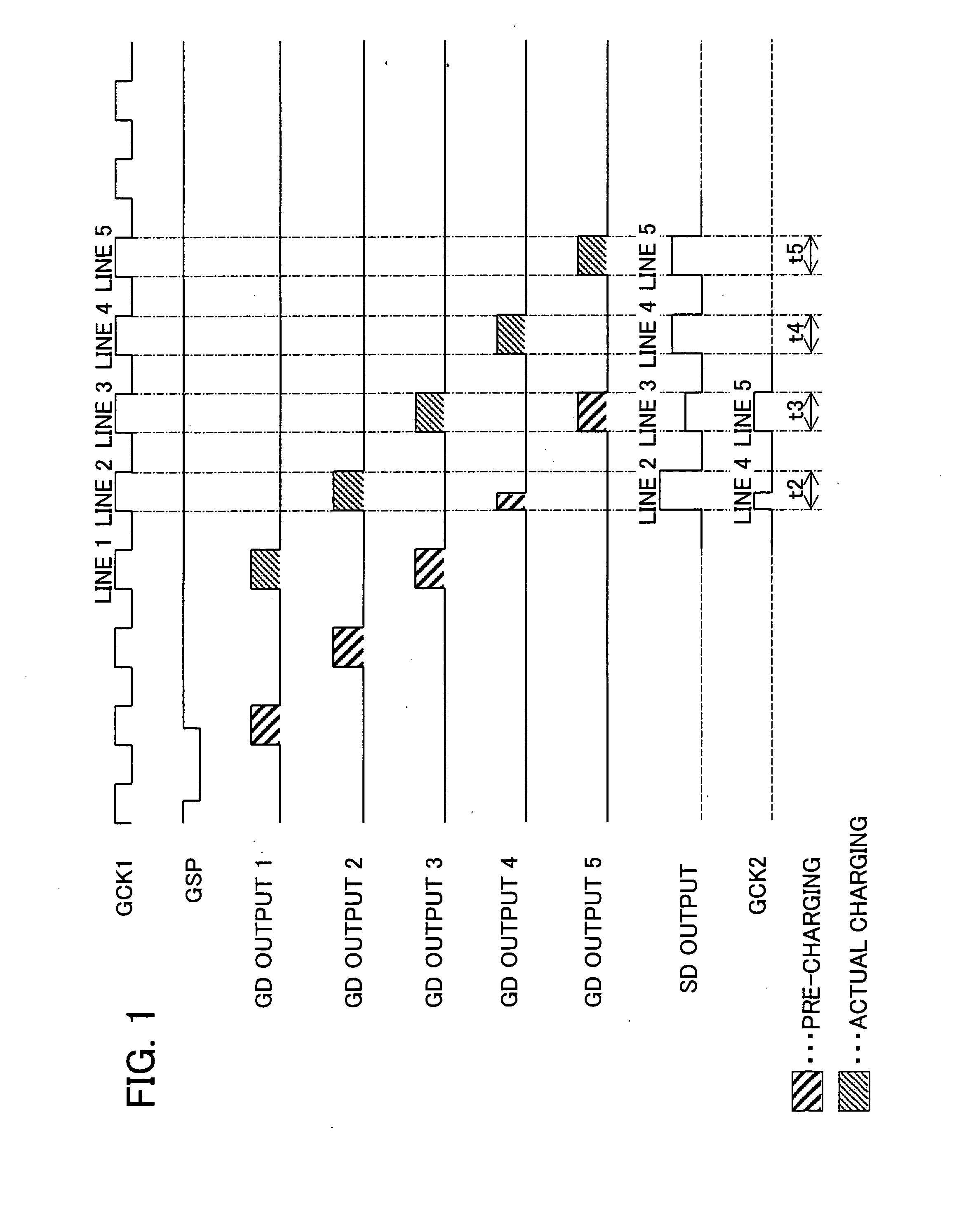
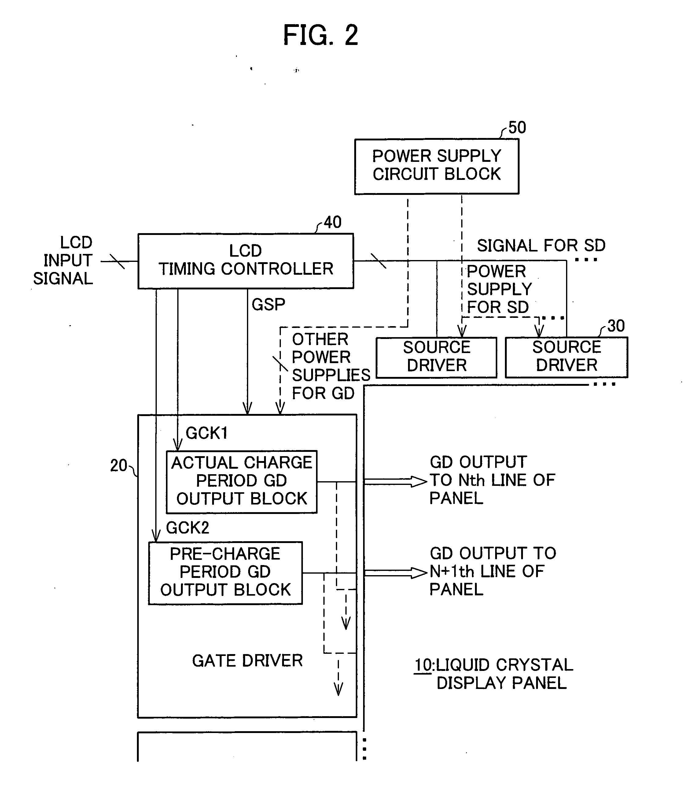
[0027] An exemplary embodiment of the present invention is explained below referring to the attached drawings. First, referring to FIG. 2, an exemplary system structure of a liquid crystal display embodying the present invention is explained.

[0028] As illustrated in FIG. 2, a liquid crystal display embodying the present invention includes a liquid crystal display panel 10, a gate driver 20, a source driver 30, an LCD timing controller 40, and a power supply circuit block 50.

[0029] The liquid crystal display panel 10 is a regular TFT liquid crystal display panel in which a plurality of gate lines and source lines are disposed intersecting each other, and a pixel is connected through TFT at each intersection of gate lines and source lines. Note that, in FIG. 2, the gate lines, source lines, TFTs and pixels are omitted from the liquid crystal display panel 10.

[0030] The gate driver 20 provides a scanning signal to a gate of each TFT through the gate lines. The source driver 30 provi...


PUM

PropertyMeasurementUnit
timeaaaaaaaaaa
chargeaaaaaaaaaa
charge levelaaaaaaaaaa

Abstract

Data (gray scale levels of source driver output) of two lines are compared between an actually charged line and a pre-charged line for which actual charging and pre-charging are carried out, respectively, during the same horizontal period. Based on the result of comparison, a pre-charged period of the pre-charged line is adjusted by adjusting a pulse width of a gate driver output. In this way, the pre-charge period is reduced and thereby overcharge is avoided in pixels which are likely to be overcharged by the pre-charging.

Description

[0001] This Nonprovisional application claims priority under 35 U.S.C. § 119(a) on Patent Application No. 61408 / 2004 filed in Japan on Mar. 4, 2004, the entire contents of which are hereby incorporated by reference. FIELD OF THE INVENTION [0002] The present invention relates to a liquid crystal display that carries out “gate-jumping two-pulse-driving.”BACKGROUND OF THE INVENTION [0003] In recent years, a resolution of TFT (Thin Film Transistor) liquid crystal displays is getting finer and finer. In this environment surrounding the TFT liquid crystal display, the available charge time for pixels, which can be regarded as a kind of a capacitor, is getting shorter. Such conditions often lead to situations where a sufficient amount of charge necessary for intended gray scale display cannot be obtained. The liquid crystal display also has a drawback that response speed is slow. [0004] One method to solve such problems is to supply a gate driver output not only to the TFTs of a line being...

Claims


Application Information

Patent Timeline
Patent Type & Authority Applications(United States)
IPC IPC(8): G02F1/133G09G3/20G09G3/36G11C7/00
CPCG02F1/13306G02F1/1362G09G3/3648G09G2320/0252G09G3/3688G09G2310/0251G09G2320/0233G09G3/3677B21C1/04B21C1/14
Inventor TAGUCHI, MINORU
Owner SHARP KK
Why Eureka
Try Eureka