Transmitting circuit, communication equipment, audio equipment, video equipment, and transmitting method

Active Publication Date: 2005-09-08
INTERDIGITAL PATENT HLDG INC
View PDF2 Cites 14 Cited by
  • Summary
  • Abstract
  • Description
  • Claims
  • Application Information

AI Technical Summary

Benefits of technology

[0020] In consideration of the above described problems, it is an object of the present invention to provide a transmitting circuit, a communication equipment, an audio equipment, a video equipment, and a transmitting method which can secure a sufficient band width and have little distortion of an output signal.
[0021] Further, in consideration of the above described problems, it is an object of the present invention to provide a transmitting circuit, a communication equipment, an audio equipment, a video equipment, and a transmitting method which can reduce the power consumption of the entire transmitting circuit and are highly efficient.
[0026] a filter, which is connected to the other terminal of said isolation unit, and reduces an unnecessary frequency component of the signals outputted from said amplifier;
[0109] a filter step of reducing an unnecessary frequency component of the signals processed by said amplifying step;
[0111] The present invention can provide a transmitting circuit, a communication equipment, an audio equipment, a video equipment, and a transmitting method which can secure a sufficient band width and have little distortion of an output signal.
[0112] Further, the present invention can provide a transmitting circuit, a communication equipment, an audio equipment, a video equipment, and a transmitting method which can reduce the power consumption of the entire transmitting circuit and are highly efficient.

Problems solved by technology

That is, there is a problem in that, because of the out of band impedance of the filter, the conventional transmitting circuit is unable to secure a sufficient band width in the amplitude modulator, and the output signal ends up being distorted.
Since such a quantization noise signal distributed in a wide frequency range is removed by the filter 1506, energy of the quantization noise is wasted, and the power consumption of the entire transmitting circuit cannot be reduced.
That is, in the conventional transmitting circuit, there is a problem in that energy of the quantization noise signal is wasted, and the power consumption of the entire transmitting circuit cannot be reduced.

Method used


Image

  • Transmitting circuit, communication equipment, audio equipment, video equipment, and transmitting method
  • Transmitting circuit, communication equipment, audio equipment, video equipment, and transmitting method
  • Transmitting circuit, communication equipment, audio equipment, video equipment, and transmitting method

Examples


first embodiment

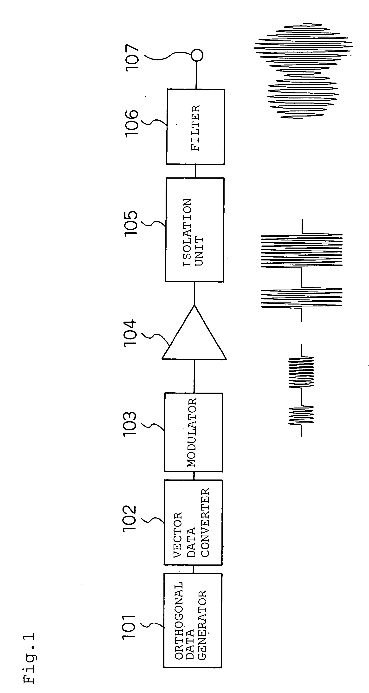
[0231] A first embodiment of the present invention will be described by using FIG. 1.

[0232] A transmitting circuit shown in FIG. 1 comprises an orthogonal data generator 101, a vector delta modulator 102, a modulator 103, an amplifier 104, an isolation unit 105, a filter 106, and an output terminal 107.

[0233] The orthogonal data generator 101 is a circuit, which generates a signal I and a signal Q which are an orthogonal data (baseband data).

[0234] The vector data converter 102 is a circuit which converts the signal I and the signal Q, and quantizises them with respect to the magnitude of the vector.

[0235] The modulator 103 is a circuit which modulates an inputted signal.

[0236] The amplifier 104 is a circuit which amplifies an inputted signal.

[0237] The isolation unit 105 is a circuit which prevents the output impedance of the amplifier 104 from being affected by the filter 106.

[0238] The filter 106 is a circuit which removes the quantization noise generated in the vector dat...

second embodiment

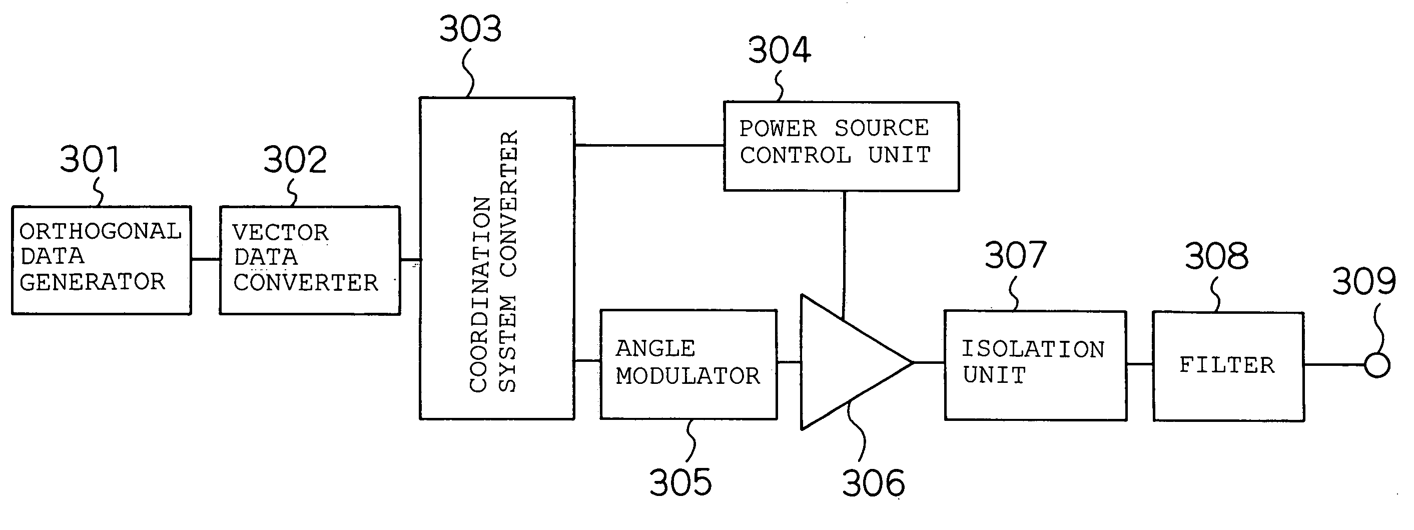
[0297] A second embodiment of the present invention will be described by using FIG. 7.

[0298] A transmitting circuit device of FIG. 7 comprises a polar data generator 401, a scalar data converter 402, a power source control unit 403, an angle modulator 404, an amplitude modulator 405, an isolation unit 406, a filter 407, and a terminal 408.

[0299] The one output of the polar data generator 401 is connected to the input of the scalar data converter 402, the output of the scalar data converter 402 is connected to the input of the power source control unit 402, and the output of the scalar data converter 402 is connected to the amplitude modulator 405. In the meantime, the other output of the polar data generator 401 is connected to the input of the angle modulator 404, and the output of the angle modulator 404 is connected to the amplitude modulator 405. The output of the amplitude modulator 405 is connected to the input of the isolation unit 406, and the output of the isolation unit ...

third embodiment

[0310] A third embodiment of the present invention will be described by using FIG. 8.

[0311] The transmitting circuit of the present third embodiment shown in FIG. 8 comprises a signal generator 501, scalar data converter 502, an amplifier 503, an isolation unit 504, a filter 505, and an output terminal 506.

[0312] The output of the signal generator 501 is connected to the input of the scalar data converter 502, and the output of the scalar data converter 502 is connected to the input of the amplifier 503. The output of the amplifier 503 is connected to the isolation unit 504, and the output of the isolation unit 504 is connected to the input of the filter 505. The output of the filter 505 is connected to the output terminal 506.

[0313] The scalar data converter 502 in the present third embodiment is an example of the signal modulation conversion circuit of the present invention.

[0314] Next, the operation of the present embodiment will be described.

[0315] The signal generator 501 ...


PUM


Abstract

The data from the orthogonal data generator is quantized by the vector data converter so as to become, for example, a binary value of 0 and a real number in magnitude. The output of the vector converter is modulated by the modulator, and is inputted to the amplifier. In the amplifier, the envelope of the signal to be inputted is quantized. That is, the signal of a constant envelope becomes a signal which is turned ON and OFF, so that a highly efficient nonlinear amplifier can be used. The quantization noise generated in the vector data converter is removed by the filter, and after that, the signal of a low distortion and a low noise is outputted from the output terminal. The isolation unit is connected between the amplifier and the filter, avoiding effects on the output impedance of the amplifier from the filter, so that a signal of a low distortion can be outputted.

Description

BACKGROUND OF THE INVENTION [0001] 1. Field of the Invention [0002] The present invention relates to a transmitting circuit, communication equipment, an audio equipment, a video equipment, and a transmitting method used in a radio apparatus such as a mobile phone, a radio LAN and the like. [0003] 2. Related Art of the Invention [0004] One example of a conventional transmitting circuit (for example, see Japanese Patent Laid-Open Publication No. 2002-325109) is shown in FIG. 27. [0005] The conventional transmitting circuit consists of a data generator 1501, a delta sigma modulator 1502, a power source control unit 1503, an angle modulator 1504, an amplitude modulator 1505, a filter 1506, and an output terminal 1507. [0006] The data generator 1501 is a circuit which outputs an amplitude data and a phase data. [0007] The delta sigma modulator 1502 is a circuit, which delta-sigma-modulates an inputted data, and outputs a data lower in resolution than the inputted data, that is, a data lo...

Claims


Application Information

Patent Timeline
IPC IPC(8): H03F1/02H03F1/26H03F1/32H03F3/217H03H17/00H04L27/04
CPCH03F1/0211H03F1/26H03F2200/331H03F3/217H03F2200/324H03F1/32
Inventor MATSUURA, TORUADACHI, HISASHI
Owner INTERDIGITAL PATENT HLDG INC
Why Eureka
Try Eureka