Transmitting circuit, communication equipment, audio equipment, video equipment, and transmitting method
a technology of transmission circuit and output signal, which is applied in the direction of generating/distributing signals, pulse techniques, instruments, etc., can solve the problems of wasting quantization noise energy, affecting the quality of output signals, so as to reduce the power consumption of the entire transmission circuit, and reduce the distortion of output signals. small
- Summary
- Abstract
- Description
- Claims
- Application Information
AI Technical Summary
Benefits of technology
Problems solved by technology
Method used
Image
Examples
first embodiment
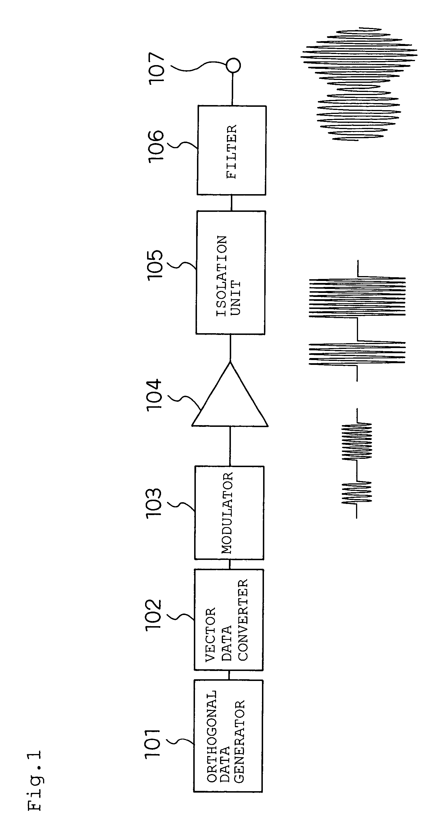
[0234]A first embodiment of the present invention will be described by using FIG. 1.
[0235]A transmitting circuit shown in FIG. 1 comprises an orthogonal data generator 101, a vector delta modulator 102, a modulator 103, an amplifier 104, an isolation unit 105, a filter 106, and an output terminal 107.
[0236]The orthogonal data generator 101 is a circuit, which generates a signal I and a signal Q which are an orthogonal data (baseband data).
[0237]The vector data converter 102 is a circuit which converts the signal I and the signal Q, and quantizises them with respect to the magnitude of the vector.
[0238]The modulator 103 is a circuit which modulates an inputted signal.
[0239]The amplifier 104 is a circuit which amplifies an inputted signal.
[0240]The isolation unit 105 is a circuit which prevents the output impedance of the amplifier 104 from being affected by the filter 106.
[0241]The filter 106 is a circuit which removes the quantization noise generated in the vector data converter 102...
second embodiment
[0300]A second embodiment of the present invention will be described by using FIG. 7.
[0301]A transmitting circuit device of FIG. 7 comprises a polar data generator 401, a scalar data converter 402, a power source control unit 403, an angle modulator 404, an amplitude modulator 405, an isolation unit 406, a filter 407, and a terminal 408.
[0302]The one output of the polar data generator 401 is connected to the input of the scalar data converter 402, the output of the scalar data converter 402 is connected to the input of the power source control unit 402, and the output of the scalar data converter 402 is connected to the amplitude modulator 405. In the meantime, the other output of the polar data generator 401 is connected to the input of the angle modulator 404, and the output of the angle modulator 404 is connected to the amplitude modulator 405. The output of the amplitude modulator 405 is connected to the input of the isolation unit 406, and the output of the isolation unit 406 i...
third embodiment
[0313]A third embodiment of the present invention will be described by using FIG. 8.
[0314]The transmitting circuit of the present third embodiment shown in FIG. 8 comprises a signal generator 501, scalar data converter 502, an amplifier 503, an isolation unit 504, a filter 505, and an output terminal 506.
[0315]The output of the signal generator 501 is connected to the input of the scalar data converter 502, and the output of the scalar data converter 502 is connected to the input of the amplifier 503. The output of the amplifier 503 is connected to the isolation unit 504, and the output of the isolation unit 504 is connected to the input of the filter 505. The output of the filter 505 is connected to the output terminal 506.
[0316]The scalar data converter 502 in the present third embodiment is an example of the signal modulation conversion circuit of the present invention.
[0317]Next, the operation of the present embodiment will be described.
[0318]The signal generator 501 outputs a m...
PUM
 Abstract
Description
Claims
Application Information
 - R&D
- Intellectual Property
- Life Sciences
- Materials
- Tech Scout
- Unparalleled Data Quality
- Higher Quality Content
- 60% Fewer Hallucinations
Browse by: Latest US Patents, China's latest patents, Technical Efficacy Thesaurus, Application Domain, Technology Topic, Popular Technical Reports.
© 2025 PatSnap. All rights reserved.Legal|Privacy policy|Modern Slavery Act Transparency Statement|Sitemap|About US| Contact US: help@patsnap.com


