
Method for producing CT images of an examination object having a periodically moving subregion

a technology of subregions and ct images, applied in tomography, instruments, applications, etc., can solve the problems of increasing the number of ct images, and affecting the accuracy of ct images

Inactive Publication Date: 2005-09-08
SIEMENS AG
View PDF4 Cites 12 Cited by
  • Summary
  • Abstract
  • Description
  • Claims
  • Application Information

AI Technical Summary

Benefits of technology

[0006] It is therefore an object of an embodiment of the invention to find a method for producing CT images of a examination object having a periodically moving subregion, preferably a beating heart. Preferably, the method reduces or, if possible, completely removes step artifacts that occur and which are produced when the total recording volume is assembled from a number of partial volumes.
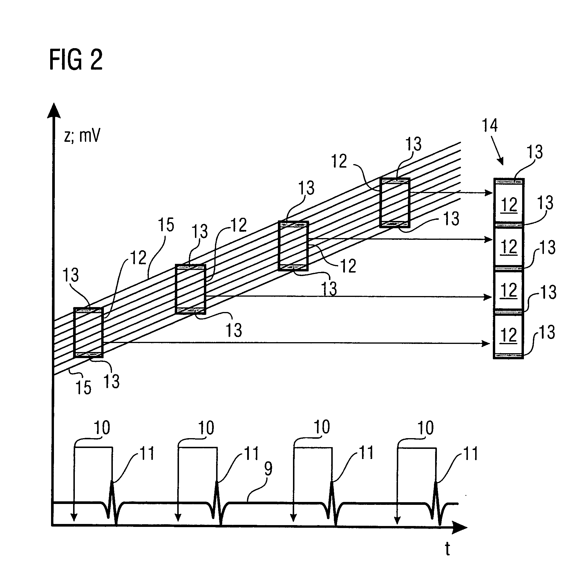
[0017] This method may largely suppress the step artifacts otherwise existing at the boundaries of the partial volumes that are produced by the assembly of the partial volumes.
[0019] The method can optionally be expanded to the effect that a threshold value limitation with an upper and a lower bound (Δ′1<Fz(x,y)<Δ′2) is applied to the error image Fz, thus producing an error image F′z that replaces the error image Fz in the further calculation method.
[0037] means are provided which during operation use the collected detector data of the rest phases to calculate axial tomograms Bz(=original images) with pixels Bz(x,y), and use the axially illustrated partial volumes to assemble the total examination volume of the examination object in the specific rest phase section by interpolative mixing, to the effect that

Problems solved by technology

This line balancing method outlined there and including median filtering, threshold value formation, differential image production and subsequent angle smoothing is not, however, suitable for the cardio CT method.
The problem additionally arises with an MPR cardio CT that the assembly of the total examination volume from partial volumes that have been measured over a number of cardiac cycles gives rise at the transition regions of the partial volumes to an increased number of step artifacts that then need additionally to be reduced.

Method used


Image

  • Method for producing CT images of an examination object having a periodically moving subregion
  • Method for producing CT images of an examination object having a periodically moving subregion
  • Method for producing CT images of an examination object having a periodically moving subregion

Examples


Embodiment Construction

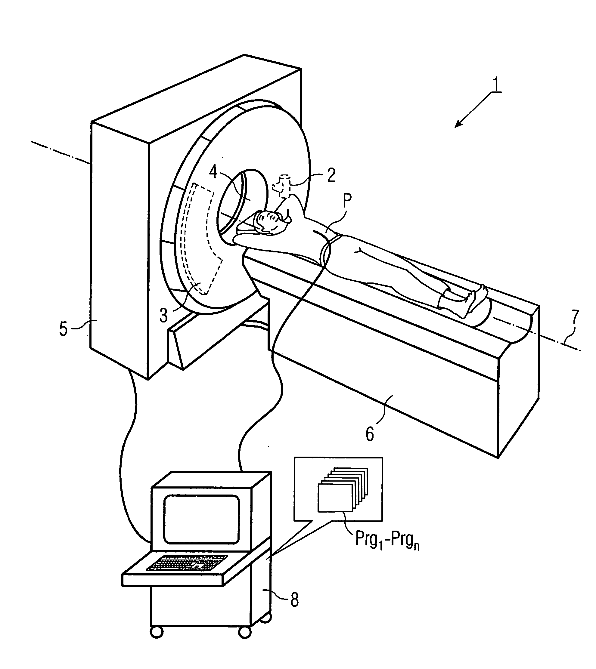
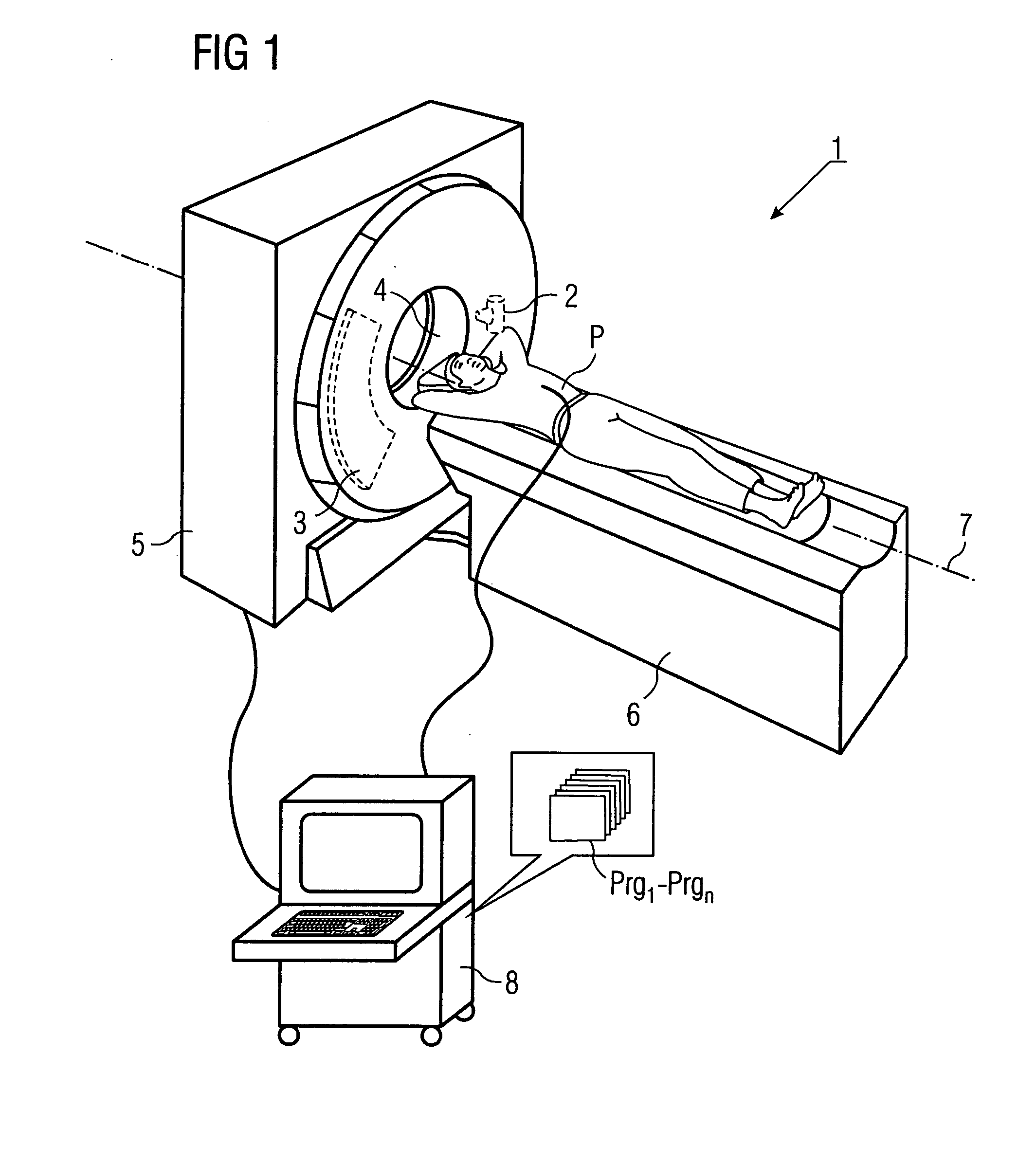
[0049]FIG. 1 shows a three-dimensional schematic of a preferred exemplary embodiment of a cardio computer tomography unit 1 having an x-ray tube 2 and an oppositely situated detector 3 that are fitted on a gantry—not illustrated—in a fashion capable of rotation inside the housing 5. The actual focus, from which the conical radiation beam scanning the patient P emerges, is situated—not visibly—inside the x-ray tube. In a fashion controlled by the control and evaluation unit 8 and the control and evaluation programs Prgn integrated therein, the patient P is moved along the z-axis 7 with the aid of the movable patient couch 6 through the opening 4 of the computer tomography unit 1, while at the same time the gantry rotates with the focus and detector about the z-axis 7. A spiral movement track of the focus, referred to the movement system of the patient, results in this way.

[0050] At the same time as the patient P is being scanned by x-rays, the movement signals of the heart are scann...


PUM


Abstract

A method and a CT unit are proposed for producing CT images of an examination object having a periodically moving subregion, preferably a beating heart, by multi-planar reconstruction. Subsequent to joining the axial images with pixels from a number of partial volumes calculated for the rest phases, a reduction takes place to reduce artifacts occurring in overlap regions. This is done by carrying out threshold value formation in the zone of the boundary regions of the partial volumes with result image Dz. A pixel-oriented median filtering then occurs, resulting in image Mz. A differential value image is then produced using Fz=Dz−Mz. Subsequently, two-dimensional lowpass filtering is applied to Fz to produce a result image Gz. Finally, a calculation of Bz−Gz is used to form the final image Ez.

Description

[0001] The present application hereby claims priority under 35 U.S.C. §119 on German patent application number DE 103 60 981.4 filed Dec. 23, 2003, the entire contents of which are hereby incorporated herein by reference. FIELD OF THE INVENTION [0002] The invention generally relates to a method for producing CT images of an examination object having a periodically moving subregion, preferably a beating heart. In such a method, the examination object may be scanned with the aid of at least one detector by at least one preferably spiral-shaped focus that is moved around this object and forms a radiation beam. At the same time, movement information of the moving subregion may be detected and stored and can be used to determine individual movement and / or rest phases. A multiplicity of tomograms doubly inclined to the system axis may be reconstructed, per cycle for partial volumes of the moving subregion, from the collected detector data, axial tomograms, perpendicular to the system axis...

Claims


Application Information

Patent Timeline
IPC IPC(8): A61B6/00A61B6/03G01N23/00G01N23/06G21K1/12H05G1/60
CPCA61B6/032A61B6/4085Y10S378/901A61B6/541A61B6/027A61B6/503
Inventor BRUDER, HERBERTFLOHR, THOMASSTIERSTORFER, KARL
Owner SIEMENS AG
Learn More