
Loop filtering method and apparatus

a filtering method and loop filter technology, applied in the field of video coding, can solve problems such as block border appearance, grid noise and staircase noise, detectable edge of image,

Active Publication Date: 2005-09-08
SAMSUNG ELECTRONICS CO LTD +1
View PDF9 Cites 58 Cited by
  • Summary
  • Abstract
  • Description
  • Claims
  • Application Information

AI Technical Summary

Benefits of technology

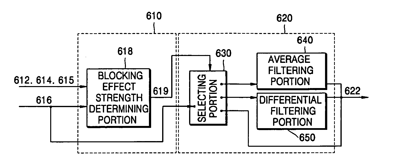
[0017] According to another aspect of the present invention, there is provided a loop filtering apparatus comprising: a blocking effect strength calculating portion calculating blocking effect strength based on coding type information, which represents a c...

Problems solved by technology

Typical problems caused by the blocking effect are grid noise and staircase noise.
Such noise causes a detectable edge of an image and may even cause a block border to appear.
The blocking effect is usually caused by a quantization error that occurs when quantization is performed in each block.
Since a large number of high-frequency coefficients in DCT are quantized to zero, the strong edge cannot be perfectly converted into a digital format in a transform field.
In addition, since an image is processed in block units during video coding, continuity of the strong edge is not secured at a block boundary.
As a result, sawtooth noise occurs at the strong edge of the image and an unnatural edge of a data block referred to as staircase noise appears.
However, conventional loop filtering is performed without considering the characteristics (e.g., characteristic edges) of an image at a block boundary, and therefore, is not suitable for high-definition digital TV which has a high resolution and a high bit rate.
Accordingly, the conventional loop filtering is not appropriate for coders utilizing Chinese digital audio and video coding standards.

Method used


Image

  • Loop filtering method and apparatus
  • Loop filtering method and apparatus
  • Loop filtering method and apparatus

Examples


Embodiment Construction

[0027] The present invention will now be described more fully with reference to the accompanying drawings in which exemplary embodiments of the invention are shown.

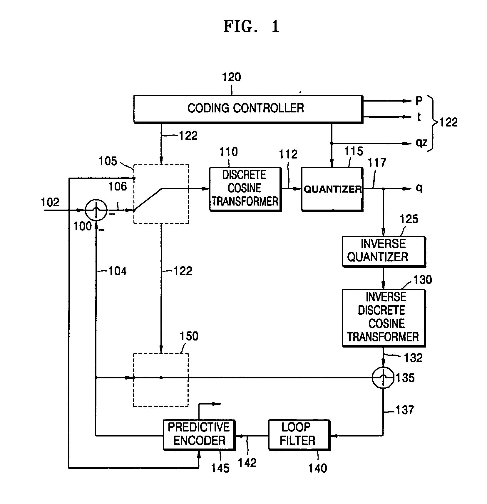
[0028]FIG. 1 is a block diagram of a video encoder. The location of a loop filter 140 in the video encoder and the functions of the loop filter 140 will be described first in the following paragraphs with reference to FIG. 1 in order to make a loop filtering method according to the present invention and the operation of the loop filter 140 more clearly understood. Referring to FIG. 1, a video signal 102 is input to a subtractor 100, a first switch 105, and a predictive encoder 145.

[0029] The subtractor 100 generates a predictive error 106 by subtracting a forward predictive value 104 (i.e., motion predictive error signal) from the input video signal and provides the predictive error 106 to the first switch 105.

[0030] The first switch 105 selects one of the predictive error 106 and the input video signal 102 in response...


PUM


Abstract

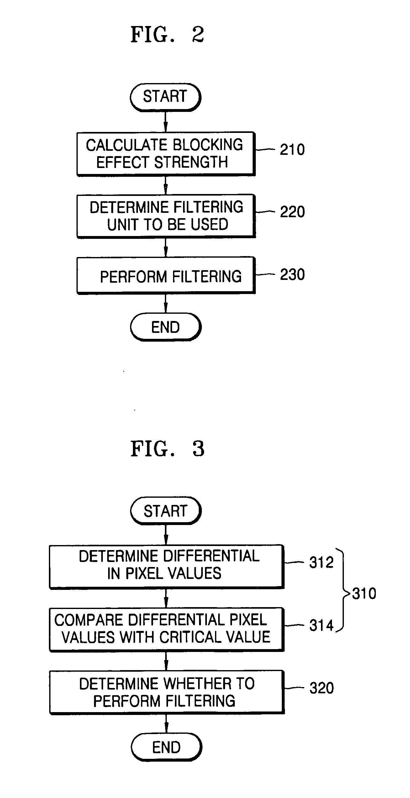
A loop filtering method and apparatus are provided. The loop filtering method includes: calculating blocking effect strength based on coding type information, which specifies the coding type of a block to be filtered, a motion vector of the block, and reference frame information, which identifies a reference frame; determining a filtering unit to be used for filtering the block based on the calculated blocking effect strength; and performing filtering on the block using the determined filtering unit. Accordingly, it is possible to provide high-quality HDTV images by determining whether to perform loop filtering and adjusting the degree of loop filtering in consideration of the characteristics of HDTV images.

Description

BACKGROUND OF THE INVENTION [0001] This application claims priority from Chinese Patent Provisional Application No. 200410012658.0, filed on Jan. 14, 2004, and Korean Patent Application No. 10-2005-0002802, filed on Jan. 12, 2005, in the Korean Intellectual Property Office, the disclosures of which are incorporated herein in their entirety by reference. [0002] 1. Field of the Invention [0003] The present invention relates to video coding, and more particularly, to a loop filtering method and a loop filter. [0004] 2. Description of the Related Art [0005] In video coding, an image is divided into blocks for processing. During such video coding, a blocking effect and a ringing effect may occur after a discrete cosine transform (DCT) and quantization are performed. The degrees of the blocking effect and the ringing effect are different in each block. [0006] Typical problems caused by the blocking effect are grid noise and staircase noise. Such noise causes a detectable edge of an image ...

Claims


Application Information

Patent Timeline
IPC IPC(8): H04N7/26H04N7/50
CPCH04N19/139H04N19/159H04N19/176H04N19/61H04N19/86H04N19/14H04N19/162H04N19/182H04N19/82H04N19/117
Inventor GUANGXI, ZHUQIANG, WENXIAOHUA, TIANXIN, JINWENYU, LIULI, YUYAO, WANG
Owner SAMSUNG ELECTRONICS CO LTD
Learn More