Eureka AIR delivers breakthrough ideas for toughest innovation challenges, trusted by R&D personnel around the world.

Rolling bearing and fan motor using the same

Inactive Publication Date: 2005-09-08
NSK LTD
View PDF6 Cites 14 Cited by
  • Summary
  • Abstract
  • Description
  • Claims
  • Application Information

AI Technical Summary

Benefits of technology

[0009] A first object of the present invention is to provide a rolling bearing, which may reduce a retainer noise even in a low-temperature environment by clarifying a relationship between a clearance gap between a pocket of a retainer and a rolling element, a base oil kinematic viscosity of grease, and the retainer noise.
[0010] A second object of the present invention is to provide a rolling bearing, which may reduce a retainer noise even in a low-temperature environment by clarifying a relationship between a clearance gap between a pocket of a retainer and a rolling element, a pour point of grease, and the retainer noise.
[0011] A third object of the present invention is to provide a rolling bearing, which may reduce a retainer noise even in a low temperature environment by clarifying a relationship between a clearance gap between a pocket of a retainer and a rolling element, a quantity of a thickener of grease and the retainer noise.

Problems solved by technology

However, in the case where the above-mentioned related-art rolling bearing is used in a low temperature environment, a base oil kinematic viscosity of grease becomes higher so that the base oil having the high kinematic viscosity irregularly flows in the clearance gap between the rolling element and the pocket, resulting in easily generating a collision noise (hereinafter referred to as retainer noise) due to collision of the rolling element and the retainer.
Further, when a grease contains a large quantity of thickener for making the base oil of grease semi-solid, the grease is liable to be solidified at a low temperature so that the fluidity is lowered to further easily generate the retainer noise.
Further, there has been a strong demand toward energy-saving of electric appliances, and the rolling bearing has been expected to be decreased in a driving torque.

Method used


Image

  • Rolling bearing and fan motor using the same
  • Rolling bearing and fan motor using the same

Examples


Embodiment Construction

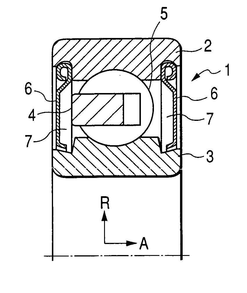
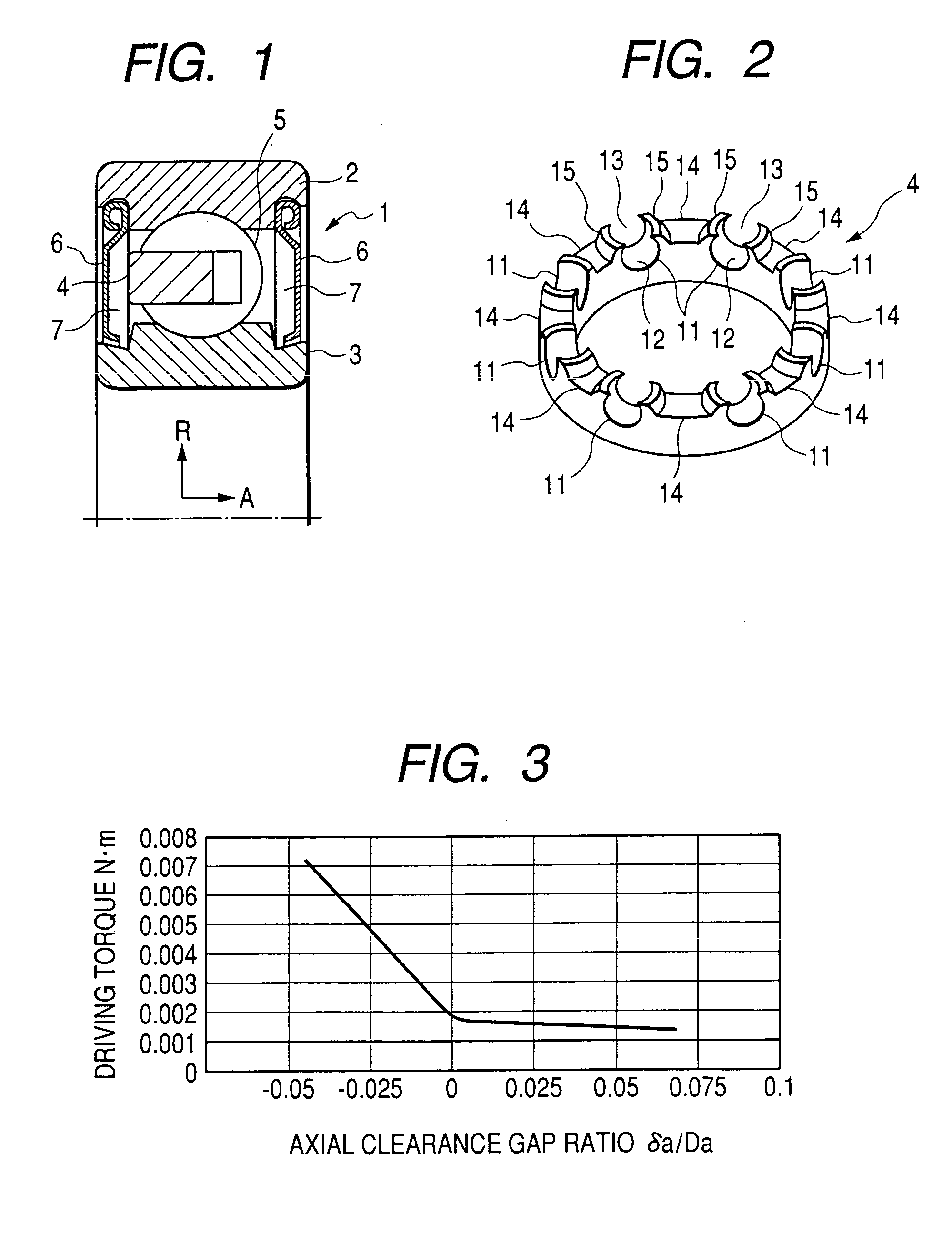
[0019] An embodiment of a rolling bearing according to the present invention will now be described with reference to the attached drawings. FIG. 1 is a half section view showing a rolling bearing according to an embodiment of the present invention, and FIG. 2 is a perspective view showing a retainer of the present invention.

[0020] In FIG. 1, a rolling bearing 1 is lubricated with a grease. The rolling bearing 1 comprises an outer ring 2 having a rolling raceway track on its inner peripheral surface and an inner ring 3 having a rolling raceway track on its the outer peripheral surface. A retainer 4 is an annular member as shown in FIG. 2 formed by injection molding of resin material.

[0021] A plurality of balls 5 as a rolling element are locked at a determined pitch in the retainer 4 to prevent mutual contact, and disposed to freely roll between the raceway track provided on the outer ring 2 and the raceway track provided on the inner ring 3 opposite thereto. Sealing plates 6 as a s...


PUM


Abstract

A rolling bearing lubricated with a grease includes an outer ring, an inner ring, a plurality of rolling elements disposed between respective rolling raceway tracks of the outer ring and the inner ring, and a retainer having a plurality of pockets for locking the rolling elements to freely roll and formed of resin material. In the rolling bearing, the radial clearance gap ratio of the pockets of the retainer is set to 0≦δr / Da≦0.09, and the axial clearance gap ratio of the pockets is set to 0≦δa / Da≦0.06 when the kinematic viscosity of base oil at 40° C. of the grease is 10 to 40 mm2 / sec, being set to 0≦δa / Da≦0.05 when the kinematic viscosity of base oil is 10 to 90 mm2 / sec, being set to 0≦δa / Da≦0.025 when the kinematic viscosity of base oil is 10 to 160 mm2 / sec.

Description

BACKGROUND OF THE INVENTION [0001] 1. Field of the Invention [0002] The present invention relates to a rolling bearing lubricated with grease and particularly to the rolling bearing for use in a fan motor. [0003] 2. Description of the Related Art [0004] A rolling bearing having a retainer made of resin has been mostly used in a motor having a fan on a shaft (hereinafter referred to as fan motor) for use in household electrical appliances such as a vacuum cleaner, a washing machine and a KOTATSU (Japanese foot warmer with frame and coverlet), air conditioning products such as air conditioners for houses and automobiles, a hot-air heater, an air cleaner, and a smoke separator, a hot-water supply device, a personal computer and measuring devices. [0005] In the rolling bearing used in the fan motor, generally an axial clearance gap ratio δa / Da of a diameter Da of a ball as a rolling element to an axial clearance gap δa provided between a pocket face of a pocket of a retainer and a rolli...

Claims


Application Information

Patent Timeline
IPC IPC(8): F16C33/38F16C33/41
CPCF16C33/416F16C2240/46F16C33/418F16C33/6633
Inventor TERADA, YASUHISATAKEI, KENJINAKA, MICHIHARU
Owner NSK LTD
Why Eureka
Eureka Blog
Learn More