Heat dissipation fan with flow guide device

a technology of flow guide and heat dissipation fan, which is applied in the direction of machines/engines, stators, liquid fuel engines, etc., can solve the problems of large amount of heat generation, degraded integral effect of computer or information product, etc., and achieve the effect of reducing offset effect, reducing eddy flow, and increasing flow rate and flow speed

Active Publication Date: 2005-09-08
ASIA VITAL COMPONENTS SHENZHEN CO LTD
View PDF3 Cites 6 Cited by
  • Summary
  • Abstract
  • Description
  • Claims
  • Application Information

AI Technical Summary

Benefits of technology

[0005] The crux of the present invention is to add an annular section to the flow guide device of a fan module so as to disperse the reversed pressure air flow and to decrease offset effect resulting from both the eddy flow and the reversed pressure air flow such that speed and flow rate of the air flow blown from the fan rotor can be increased for removing the heat of the electronic component speedily and maintaining the electronic component in a normal running state.
[0006] Accordingly, an object of the present invention is to provide a heat dissipation heat fan with flow guide device to decrease eddy flow under the flow guide device and increase flow rate and flow speed of downward air flow blown by the fan rotor.

Problems solved by technology

When the electronic component is under operation, a large quantity of heat may generate to affect the smooth operation of the electronic component if the heat is not removed in time effectively.
As a result, integral effect of the computer or the information product becomes degraded.

Method used


Image

  • Heat dissipation fan with flow guide device
  • Heat dissipation fan with flow guide device
  • Heat dissipation fan with flow guide device

Examples


first embodiment

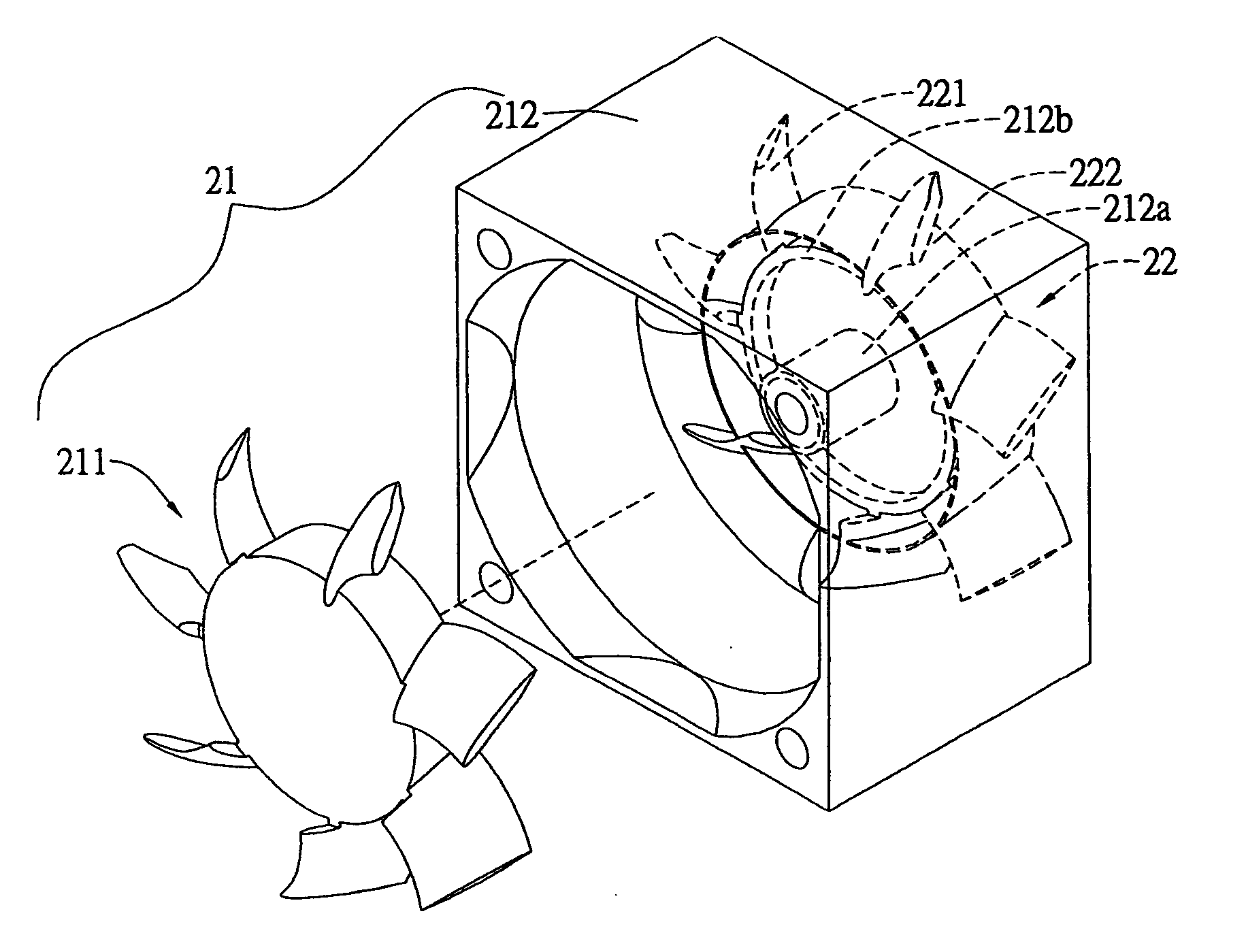
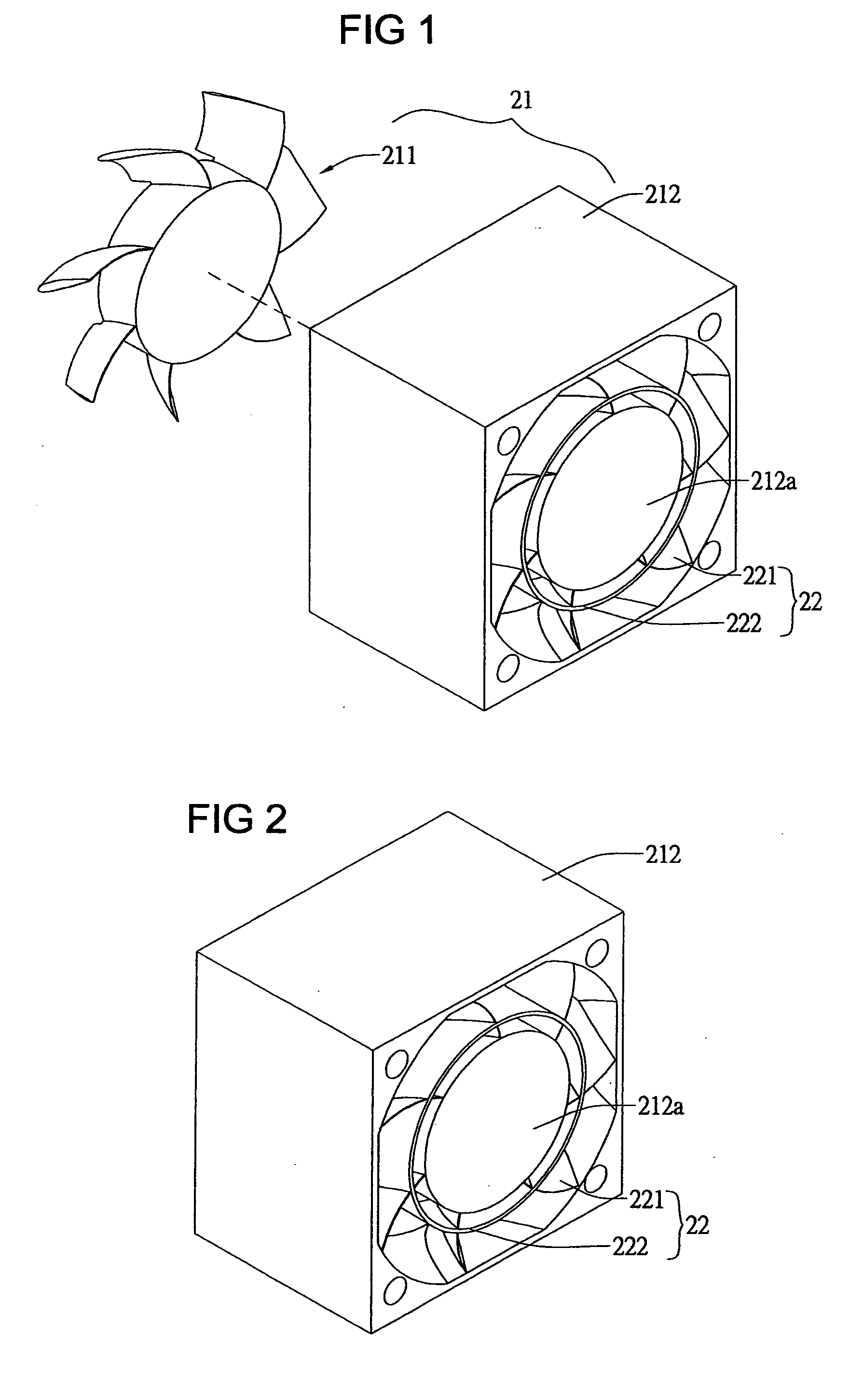
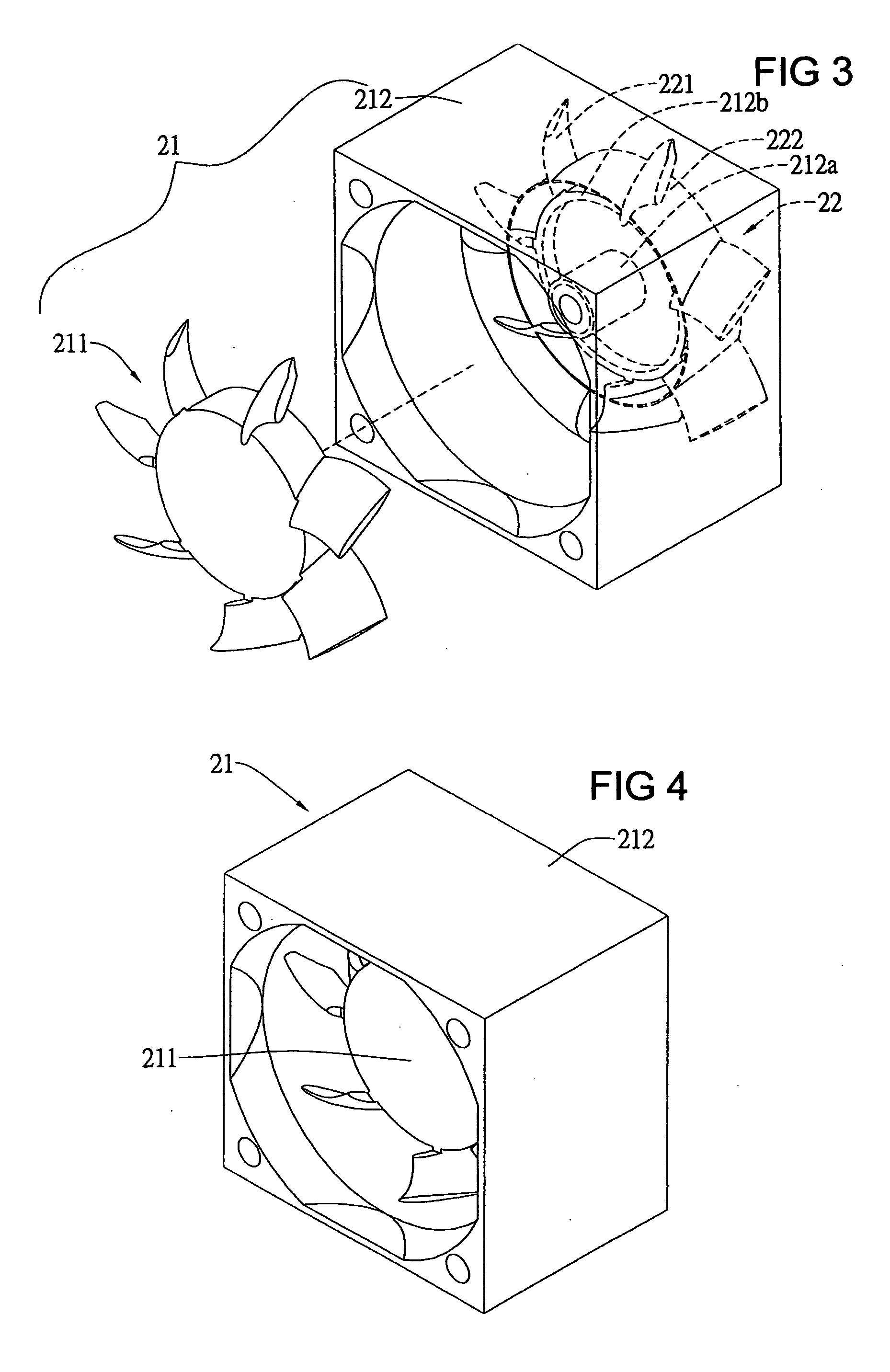
[0023] Referring to FIGS. 1 to 6, a heat dissipation fan with flow guide device according to the present invention in the first embodiment thereof includes a fan module 21 and a flow guide device 22. The fan module 21 further includes a fan rotor 211 and a motor stator set 212. The motor stator set 212 provides an axial core 212a and an annular join part 212b. The flow guide device 22 is composed of a plurality of flow guide blades 221 and the flow guide blades 221 is integrally made as a piece. The flow guide blades 221 are provided with an annular section 222 with a slant 222a and the annular section 222 forms at the inner side thereof a annular space 222b.

[0024] The fan rotor 211 is rotationally joined to the axial core 212a of the motor stator set 212 and the annular section 222 is disposed to surround the flow guide blades 221. The slant 222a is capable of increasing the speed of the air flow and guide air direction.

[0025] Once the fan module 21 is powered on, the air flow ge...

second embodiment

[0027] Referring to FIGS. 9 to 14, a heat dissipation fan with flow guide device according to the present invention in the second embodiment thereof includes a fan module 31 and a flow guide device 31. The fan module 31 further includes a fan rotor 311 and a motor stator set 312. The motor stator set 312 is provided with an axial core 312a and an annular join part 312b. The flow guide device 32 is composed of a plurality of guide air blades 321, which are integrally made with a frame 323 and disposed to surround the frame 323. An annular section 322 is disposed on the flow guide blades 321 and a slant 322a is at the upper edge of the annular section 322 and an annular space 322b is formed at the inner side of the annular section 322.

[0028] The fan rotor 311 is rotationally joined to axial core 312a of the motor stator set 312 and the annular section 322 is disposed to surround the flow guide blades 321a of the guide air device 32. The slant 322a at the upper edge of the annular part...


PUM


Abstract

A heat dissipation fan includes a fan module and a flow guide device. The fan module further includes a motor stator set and a fan rotor. The motor stator set provides an axial core and an annular join part. The fan rotor is rotationally joined to the axial core. The flow guide device provides a plurality of flow guide blades. An annular section is provided on the flow guide blades and the flow guide blades is integrally made with the annular join part or the flow guide blades is integrally made with a frame and the frame being attached to the motor stator set. The annular section can reduce an eddy flow area, which is formed due to an electronic component impeding the air flow and creating counter air flow under the flow guide blades, so as to increase flow speed and flow rate of the air flow blown by the fan rotor and approaching an electronic component.

Description

BACKGROUND OF THE INVENTION [0001] 1. Field of the Invention [0002] The present invention relates to a heat dissipation fan with flow guide device and particularly to a heat dissipation fan, which is provided with an annular part to reduce the eddy flow under the flow guide blades. [0003] 2. Brief Description of Related Art [0004] When the electronic component is under operation, a large quantity of heat may generate to affect the smooth operation of the electronic component if the heat is not removed in time effectively. As a result, integral effect of the computer or the information product becomes degraded. In order to remove the heat effectively, usually a metal radiator and a cooling fan are added to the electronic component to speed up removal of the heat. Taiwanese Patent Publication No. 523652, entitled “COMPOSITE TYPE FAN WITH HEAT DISSIPATION FRAME”, provides a first frame and a first flow guide part. The first flow guide part is attached to the first frame and composed of...

Claims


Application Information

Patent Timeline
Patent Type & Authority Applications(United States)
IPC IPC(8): F01D9/00
CPCF04D29/541
Inventor SUN, SUNG-WEI
Owner ASIA VITAL COMPONENTS SHENZHEN CO LTD
Why Eureka
Try Eureka