Articulated bench

a technology of articulating and supporting posts, which is applied in the field of supporting posts, can solve the problems of reducing the utility of the lloyd massage table, compromising the utility of the wolff, larossa et al., stevens devices for non-weightlifting purposes, and the inability to collapsible/fold apparatus, etc., and achieves a broader range of positions. , the effect of increasing the total number o

Inactive Publication Date: 2005-09-08
PARKER JAMES
View PDF9 Cites 17 Cited by
  • Summary
  • Abstract
  • Description
  • Claims
  • Application Information

AI Technical Summary

Benefits of technology

[0021] The present apparatus also includes improved support leg assemblies for attaining an exponentially wider range of inclines. One each of the support leg assemblies is pivotally mounted at each end of the frame. The two support leg assemblies include primary foot cross-bars, may be independently pivoted outward from an inwardly-stowed position to a deployed position for resting on the feet cross-bars. In addition, both of the support leg assemblies include a secondary foot crossbar that is fixedly attached to the leg approximately halfway between the primary foot crossbar and the point of pivoting. These secondary foot crossbars either provide lateral floor-support to the frame when the support leg assembly is locked in the inwardly stowed position, or when deployed at approximately a 110 degree angle (away from the frame) serve as a hand hold or foot rest for use while performing the activities associated with the present invention, thereby allowing a broader range of positions and much greater utility to the bench. The support leg assemblies pivot about axles affixed to the frame and are locked in either the outwardly extended, or inwardly stowed positions via a snap pin / bracket assembly. Thus, in the preferred embodiment to be described where the length-adjustable dual tubular brace assembly can be locked in any of four positions, and the second end of the brace assembly may be inserted into either of two pairs of catches located on the pivoting padded section's rear surface (or left flat and unattached), it becomes possible to set the padded section in any of nine angular positions, beginning at horizontal. Moreover, since either support leg assembly can be folded inward and locked such that the end of the frame may be inclined downward and supported on the secondary foot crossbar, the number of angular positions for the padded sections is effectively tripled to twenty-seven. Of course, the total number of incline positions may be increased by increasing the number of locked positions of the telescoping tubular brace assembly, or by increasing the number of pairs of catches located on the pivoting padded section's rear surface.
[0022] The frame construction combined with the design of the support leg assemblies result in an articulated bench with maximum number of incline positions, increased lateral stability in all such positions, and yet reduced manufacturing costs.
[0023] The articulated bench of the present invention is fabricated of a variety of strong, light-weight materials to provide the durability and portability required by the nature of its usage. The present invention's design is simple and straightforward, and can be economically manufactured.

Problems solved by technology

Unfortunately, the prior art devices of Lloyd, Wolff, Christie, LaRossa et al., and Stevens possess designs specific to use either for massage or weightlifting purposes.
The massage table of Lloyd, while collapsible, does not provide the upper / lower body support in an inclined position required by weightlifting or other exercise programs.
The utility of the Wolff, Christie, LaRossa et al., and Stevens devices for non-weightlifting purposes is compromised by the presence of barbell support posts.
The Isom et al. apparatus is not collapsible / foldable and does not provide adjustment of the back rest that is independent of the position of a bottom rest.

Method used


Image

  • Articulated bench
  • Articulated bench
  • Articulated bench

Examples


Embodiment Construction

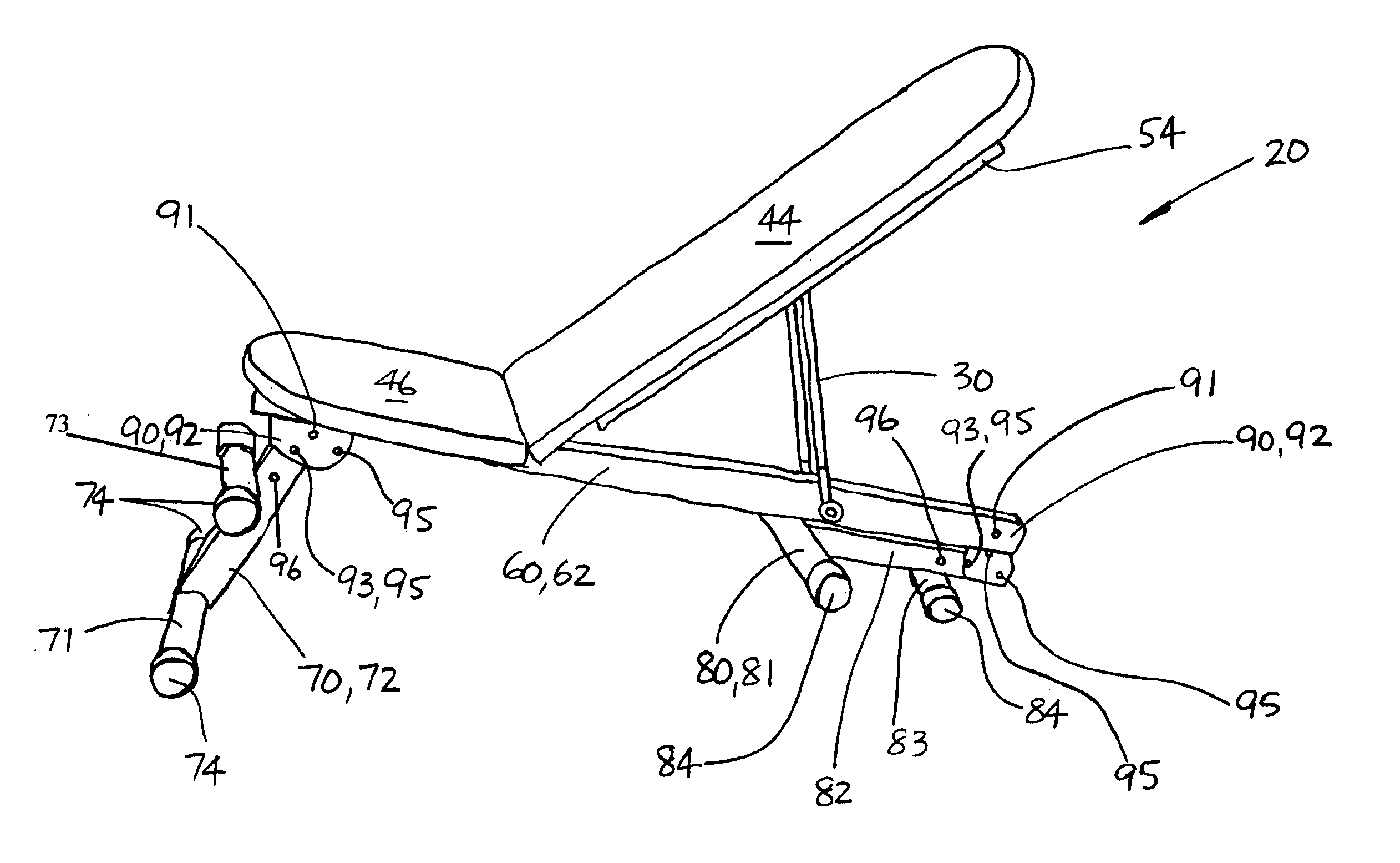
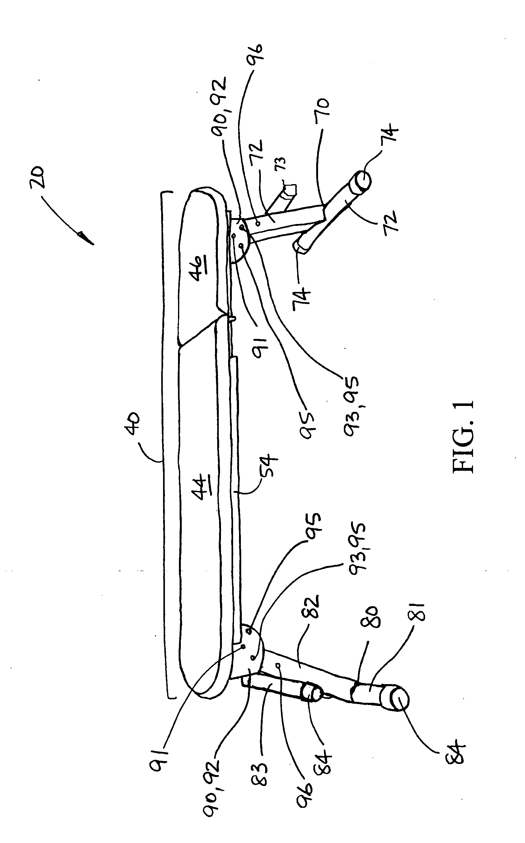
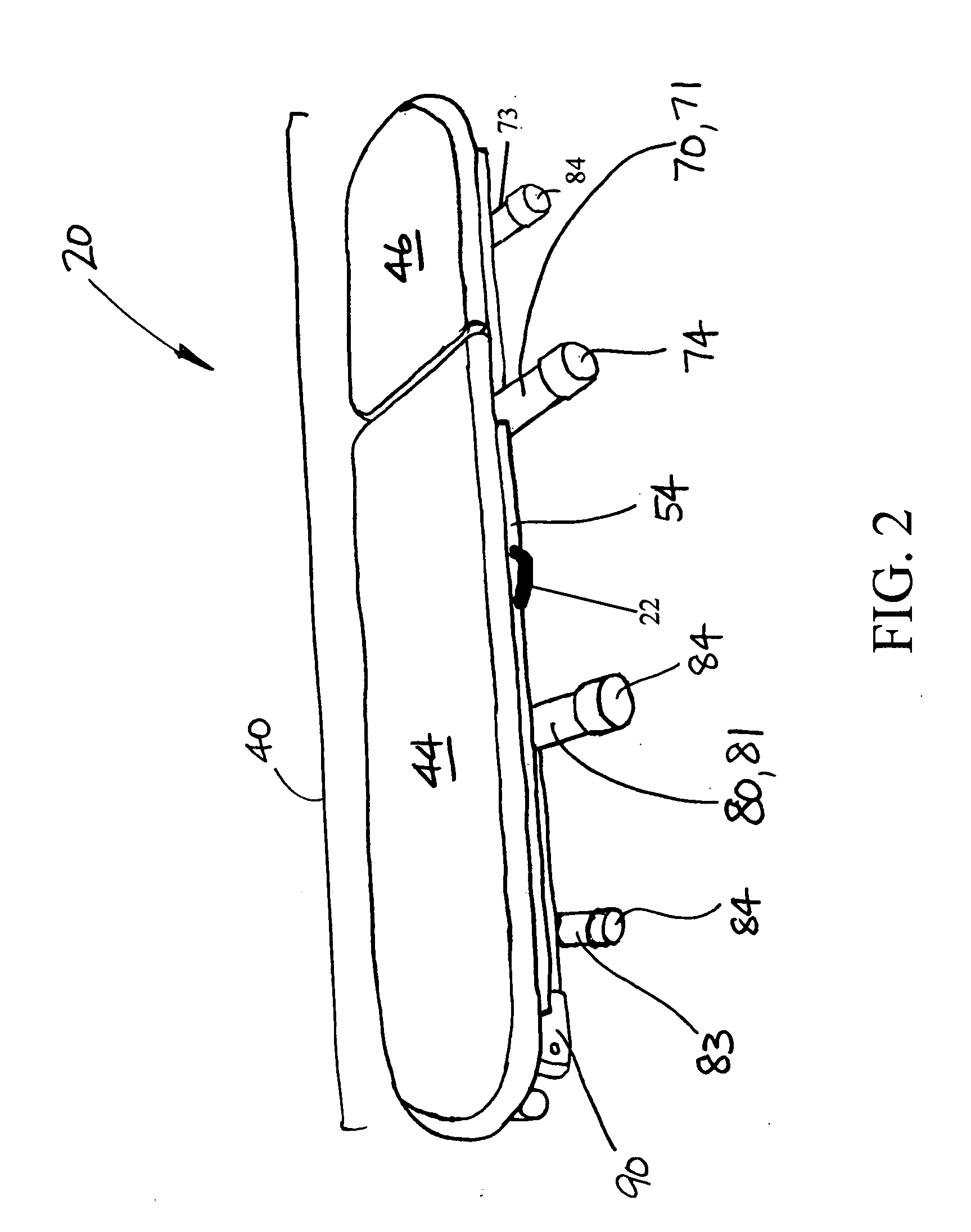
[0033]FIG. 1 is a side perspective view of an articulated bench 20 according to a first embodiment of the present invention. FIGS. 2 and 3 are, respectively, top and bottom perspective views of the articulated bench 20 of FIG. 1 shown in a fully collapsed configuration. FIGS. 4 and 5 are, respectively, side and rear perspective views of the articulated bench 20 of FIGS. 1-3 shown in one of its many erect configurations.

[0034] As seen in FIGS. 1-3, the articulated bench 20 according to the present invention generally comprises a two-section supporting surface 40, a frame 60, and two folding / pivoting support leg assemblies 70, 80.

[0035] Referring to FIGS. 3 and 5, the frame 60 is preferably a fixed assembly configured in the form of a cross and including lengthwise member 62 and cross member 63 (see FIG. 5). The lengthwise member 62 is preferably fabricated of steel or aluminum tubular stock for increased structural strength, the stock being cut to an appropriate length. The cross m...


PUM


Abstract

An articulated bench comprising a two-section pad and two folding/pivoting support leg assemblies attached to a frame. A length-adjustable (telescoping) dual tubular brace assembly folds out of the frame from beneath the pivoting padded section (i.e. the section for supporting the upper body) and is inserted into one of a series of catches located on the section's rear surface to hold it at a selectable incline. Improved pivoting support leg assemblies include primary foot cross-bars, and secondary foot crossbars each fixedly attached to a leg to either provide lateral floor-support when the support legs are locked in the inwardly stowed position, or alternatively serve as a hand holds or foot rests when the legs are deployed for performing exercises, thereby allowing a broader range of positions and much greater utility. Since either support leg assembly can be folded inward and locked such that the end of the frame may be inclined downward and supported on the secondary foot crossbar, the number of angular positions for the padded sections is effectively tripled.

Description

CROSS-REFERENCE TO RELATED INVENTION(S) [0001] The present application derives priority from U.S. Provisional Patent Application 60 / 538,542; filed: Jan. 23, 2004.BACKGROUND OF THE INVENTION [0002] 1. Field of the Invention [0003] The present invention relates to support benches such as utilized during body toning, weight training, and other therapeutic activities and, more particularly, to a portable, fully-articulated, multi-purpose bench. [0004] 2. Description of the Background [0005] Many different activities such as body toning, weight training, weight-lifting, and other therapeutic and / or athletic activities require the use of a supporting structure capable of supporting the body in a variety of positions. For example, for an effective workout a weight lifter must exercise all major muscle groups by placing themself in a variety of positions ranging from flat-on-his / her-stomach, to reclining, to flat-on-his / her-back, and all at a height that provides a full range of arm or leg ...

Claims


Application Information

Patent Timeline
Patent Type & Authority Applications(United States)
IPC IPC(8): A63B26/00
CPCA63B21/1457A63B21/4029
Inventor PARKER, JAMES
Owner PARKER JAMES
Why Eureka
Try Eureka