
Device and method for generating a complex spectral representation of a discrete-time signal

a discrete-time signal and complex technology, applied in the field of timefrequency conversion algorithms, can solve the problems of severe limitation of the achievable spectral splitting quality, undesired data compression methods, and the approach is subject to some limitations

Active Publication Date: 2005-09-08
FRAUNHOFER GESELLSCHAFT ZUR FOERDERUNG DER ANGEWANDTEN FORSCHUNG EV
View PDF4 Cites 80 Cited by
  • Summary
  • Abstract
  • Description
  • Claims
  • Application Information

AI Technical Summary

Benefits of technology

[0031] It has been found out according to the invention that a combination of real spectral coefficients in temporal and/or frequency proximity to the complex spectral coefficient to be determined provides a good approximation to a desired frequency response of the entire assembly from the means for generating a block-wise real-valued spectral representation and the means

Problems solved by technology

This approach, however, is subject to some limitations.
Otherwise, L values in the spectral representation would have to be transferred with a temporal offset of N<L values for N respective new input values of the DFT, which is particularly undesired in data compression methods.
The usage of non-overlapping window functions, however, means a severe limitation of the achievable spectral splitting quality, wherein especially the separation of different frequency bands is to be mentioned.
Such a procedure correspondingly provides bad approximations for short-term magnitude spectra of the input signal.
It has been found out that even this approximation of a complex spectrum from a real-valued spectral representation of the discrete-time input signal is problematic in that an adequate magnitude representation cannot be obtained for sounds of certain frequencies.
Determining short-term magnitude spectra is thus only possible with this transform to a limited extent.

Method used


Image

  • Device and method for generating a complex spectral representation of a discrete-time signal
  • Device and method for generating a complex spectral representation of a discrete-time signal
  • Device and method for generating a complex spectral representation of a discrete-time signal

Examples


Embodiment Construction

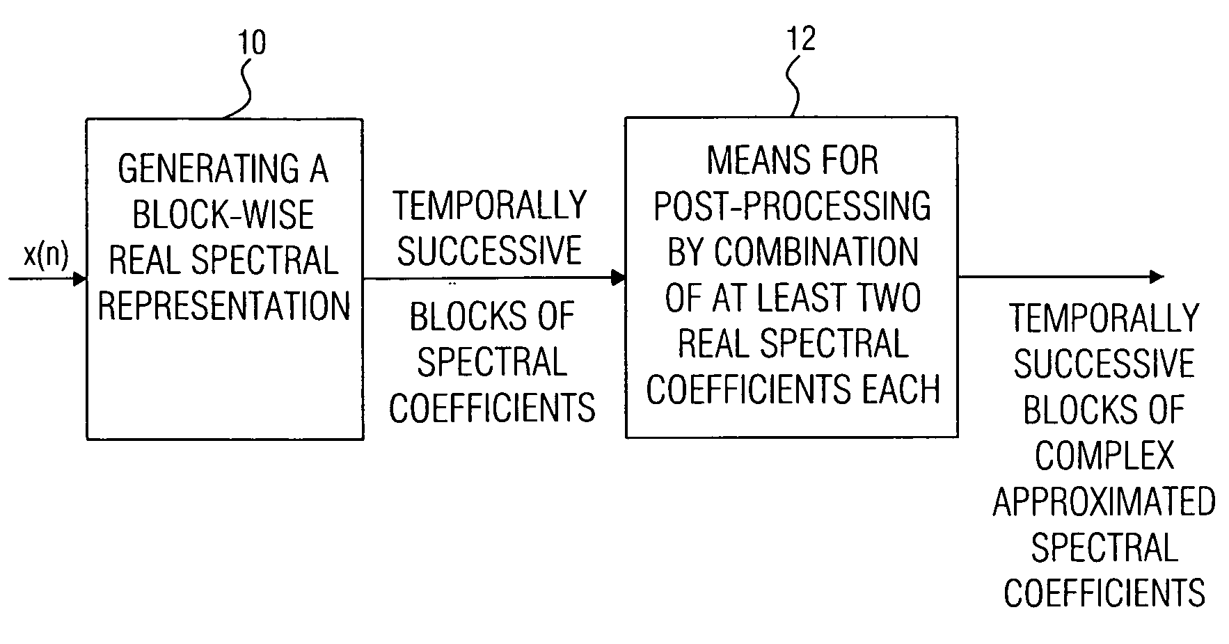
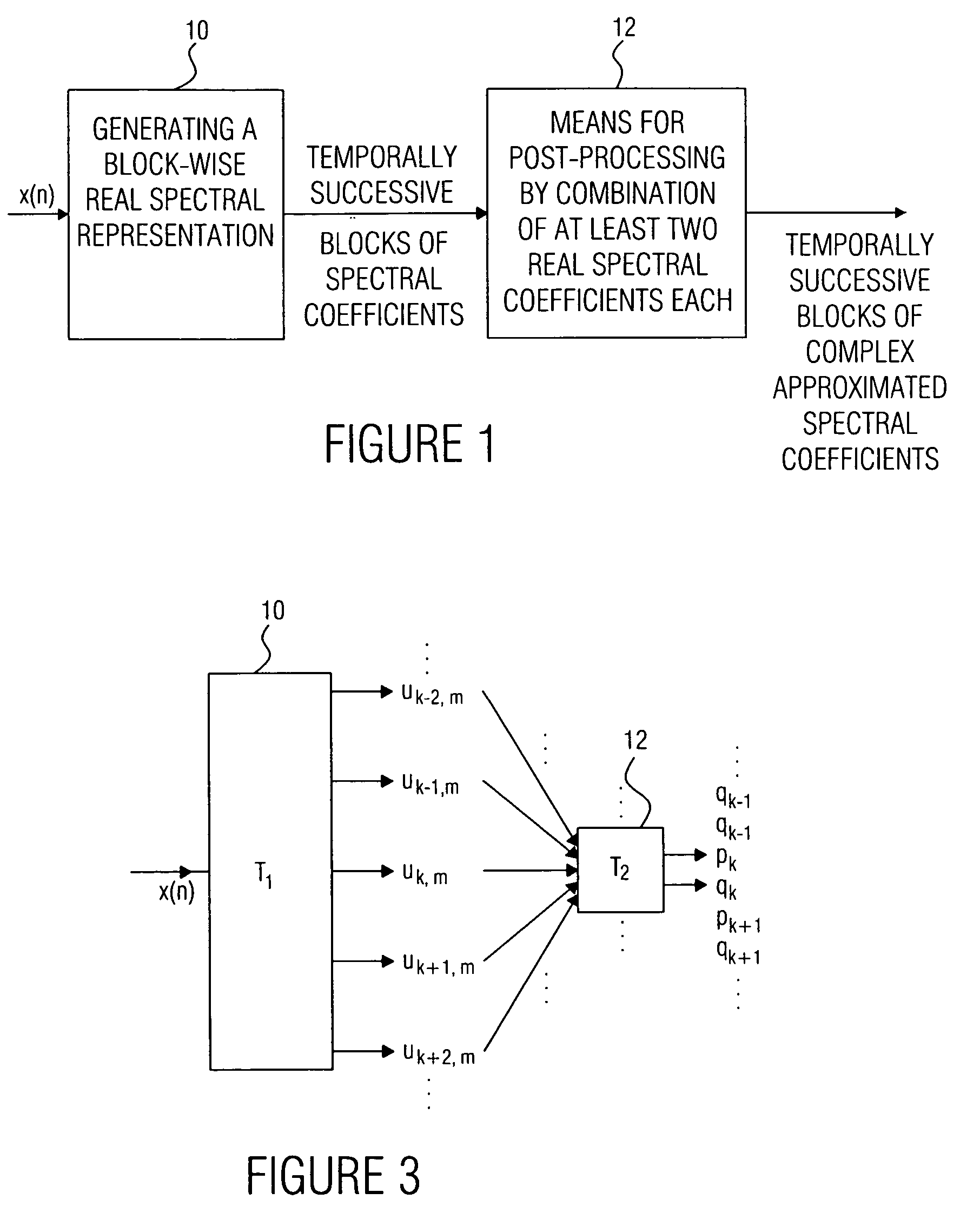
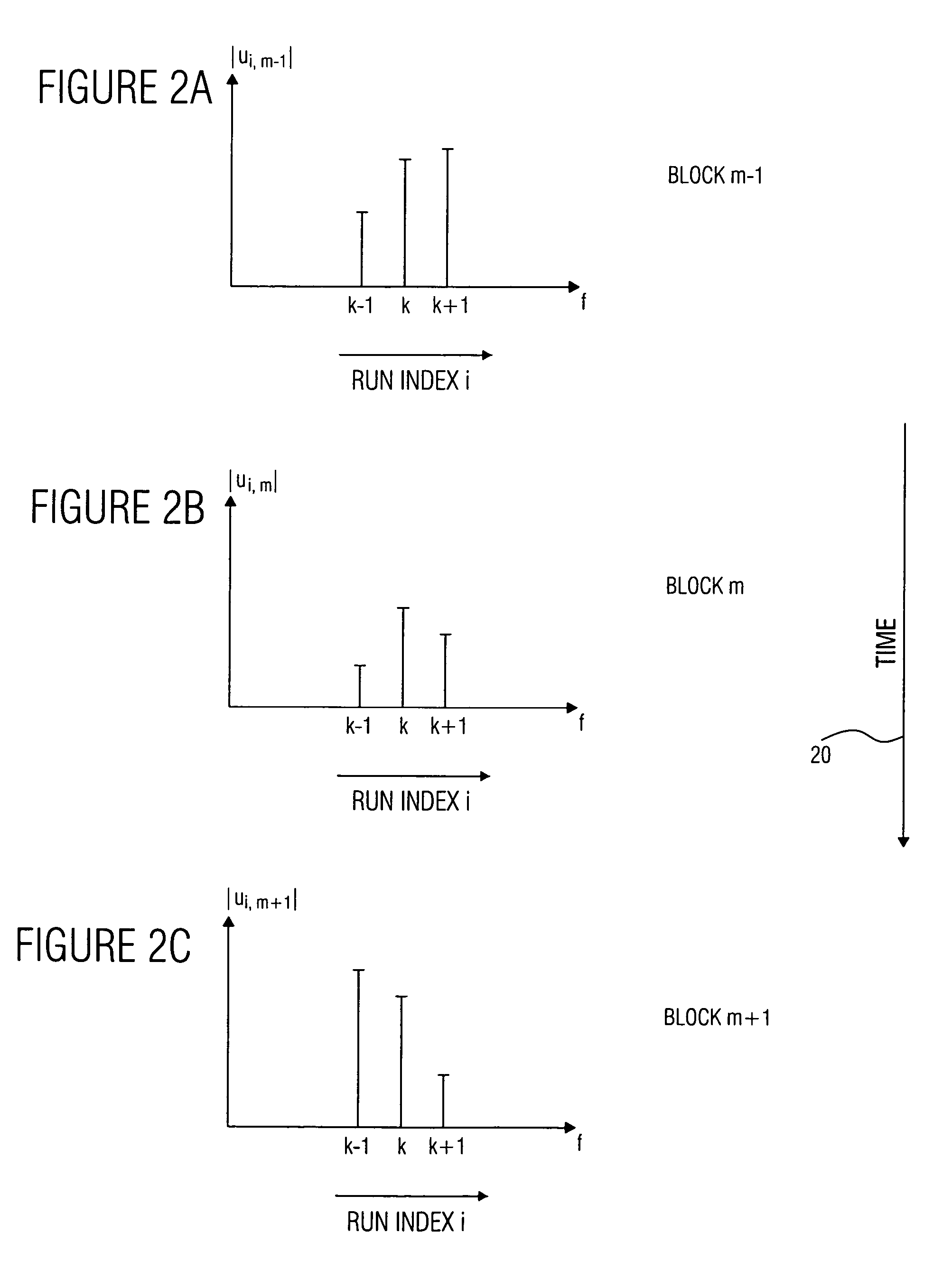
[0040]FIG. 1 shows a device for generating a complex spectral representation of a discrete-time signal x(n). The discrete-time signal x(n) is fed to means 10 for generating a block-wise real-valued spectral representation of the discrete-time signal, the spectral representation comprising temporally successive blocks, each block comprising a set of spectral coefficients, as will be discussed in greater detail referring to FIGS. 2a and 2b. At the output of means 10, there is a sequence of temporally successive blocks of spectral coefficients which, due to the characteristic of means 10, are real-valued spectral coefficients. This sequence of temporally successive blocks of spectral coefficients is fed to means 12 for post-processing to obtain a block-wise complex approximated spectral representation comprising successive blocks, each block comprising a set of complex approximated spectral coefficients, wherein a complex approximated spectral coefficient can be represented by a first ...


PUM


Abstract

A filter bank device for generating a complex spectral representation of a discrete-time signal includes a generator for generating a block-wise real spectral representation, which, for example, implements an MDCT, to obtain temporally successive blocks of real spectral coefficients. The output values of this spectral conversion device are fed to a post-processor for post-processing the block-wise real spectral representation to obtain an approximated complex spectral representation having successive blocks, each block having a set of complex approximated spectral coefficients, wherein a complex approximated spectral coefficient can be represented by a first partial spectral coefficient and by a second partial spectral coefficient, wherein at least one of the first and second partial spectral coefficients is determined by combining at least two real spectral coefficients. A good approximation for a complex spectral representation of the discrete-time signal is obtained by combining two real spectral coefficients, preferably by a weighted linear combination, wherein additionally more degrees of freedom for optimizing the entire system are available.

Description

CROSS-REFERENCE TO RELATED APPLICATION [0001] This application is a continuation of copending International Application No. PCT / EP03 / 07608, filed Jul. 14, 2003, which designated the United States and was not published in English, and is incorporated herein by reference in its entirety.BACKGROUND OF THE INVENTION [0002] 1. Field of the Invention [0003] The present invention relates to time-frequency conversion algorithms and, in particular, to such algorithms in connection with audio compression concepts. [0004] 2. Description of the Related Art [0005] A representation of real-valued discrete-time signals in the form of complex-valued spectral components is required for some applications when coding for the purpose of compressing data and, in particular, when audio-coding. A complex special coefficient can be represented by a first and second partial spectral coefficients, wherein, as is desired, the first partial spectral coefficient is the real part and the second partial spectral ...

Claims


Application Information

Patent Timeline
IPC IPC(8): G10L25/18G10L25/48H03M7/30
CPCG10L25/18G10L19/00G10L25/48
Inventor EDLER, BERNDGEYERSBERGER, STEFAN
Owner FRAUNHOFER GESELLSCHAFT ZUR FOERDERUNG DER ANGEWANDTEN FORSCHUNG EV
Learn More