Machining tool and method for repair of rotor teeth in a generator

a technology of machining tools and rotor teeth, which is applied in the direction of manufacturing tools, metal-working machine components, vibration drilling, etc., can solve the problems of rotor teeth forming cracks, the dovetail surface of rotor teeth may crack, so as to achieve the effect of improving the quality of work

Inactive Publication Date: 2005-09-15
GENERAL ELECTRIC CO
View PDF15 Cites 47 Cited by
  • Summary
  • Abstract
  • Description
  • Claims
  • Application Information

AI Technical Summary

Problems solved by technology

During long term operation of the generator (such as during decades of operation), the dovetail surfaces on rotor teeth may crack due wear of the wedges abutting against the teeth.
Cracks tend to form in teeth that have slots that had been capped with hard metal wedges.
Cracks are most likely to form on the upper surfaces of the dovetail section of the a rotor tooth.
If no...

Method used


Image

  • Machining tool and method for repair of rotor teeth in a generator
  • Machining tool and method for repair of rotor teeth in a generator
  • Machining tool and method for repair of rotor teeth in a generator

Examples


Embodiment Construction

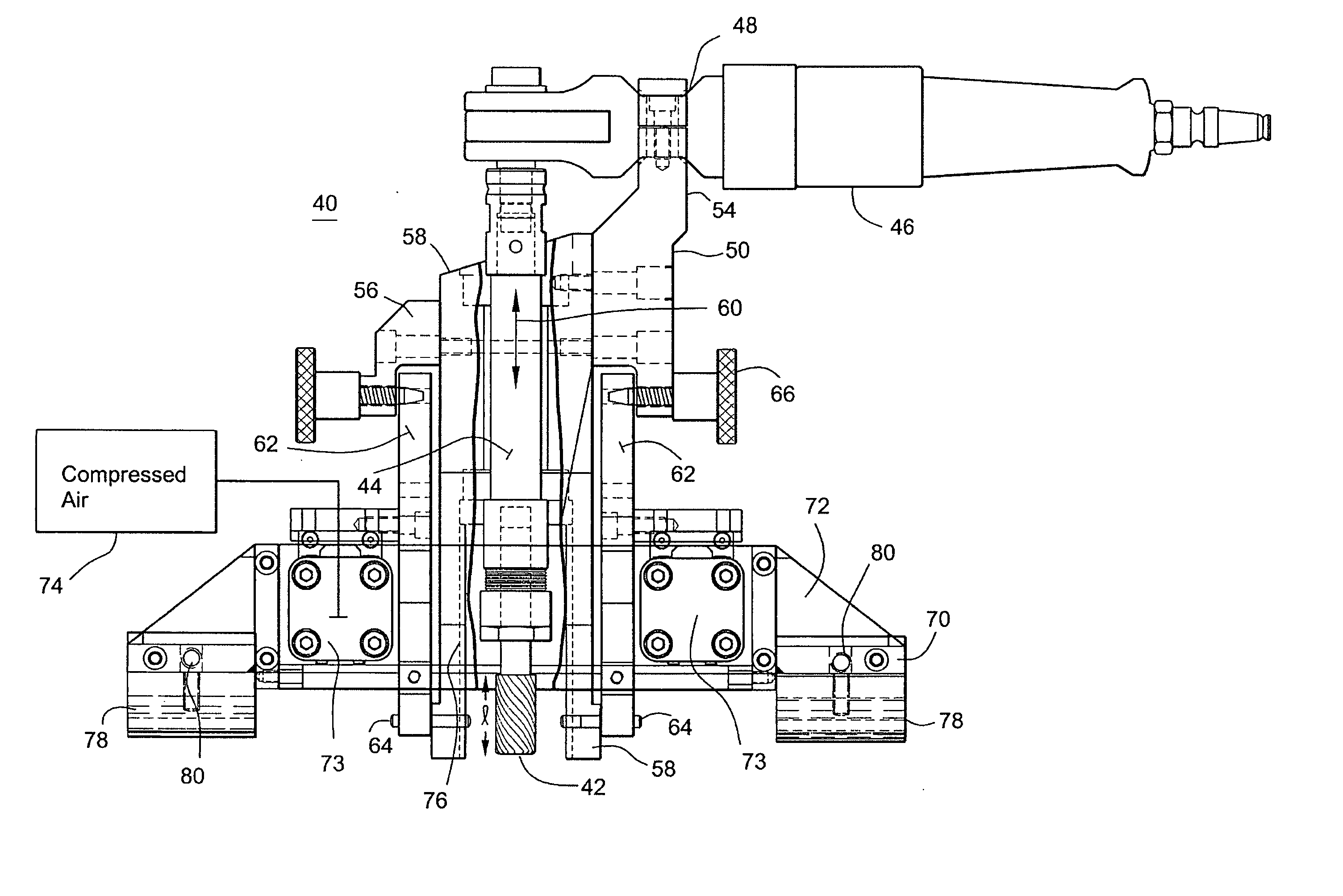
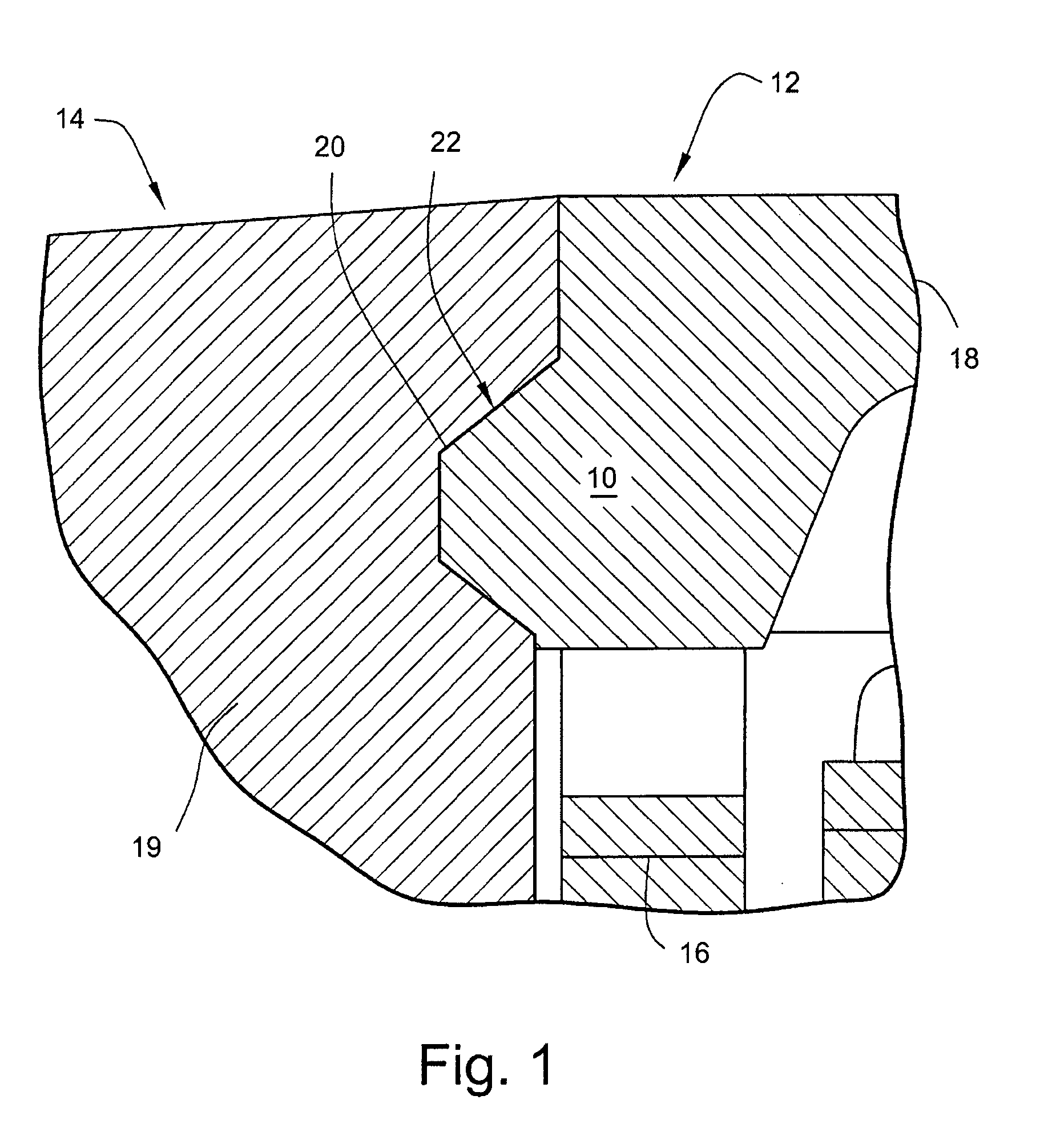
[0020]FIG. 1 is an enlarged cross-sectional view of the dovetail section 10 of a rotor slot 12 that is cut radially inward along the longitudinal length of a rotor 14. Conductive windings 16 are mounted in the rotor slot 12. A wedge 18 caps the winding in the slot and mounts in the slot at the dovetail section 10. The wedge 18 has extended side surfaces that engage the rotor slot surfaces at the dovetail sections 20. The metal row between adjacent slots are the teeth 19 of rotor. The side surfaces of the teeth define the slots. The dovetail surfaces 20 of the rotor teeth tend to be heavily loaded by centrifugal and vibration forces because wedges 18 abut against the dovetail surfaces 20 of the teeth 19.

[0021] Over the course of many years of rotational operation of a power generator, the vibration and forces acting between the wedge and the rotor teeth can induce cracks in the dovetail sections 20 of the teeth. In particular, inspection of certain rotors which have been in continuo...


PUM


Abstract

A machine cutter including a cutting bit positionable in a slot of a machine; a drive shaft rotatably driving the bit; a bracket having a plurality of angular positions for supporting and pivoting the bit wherein bit pivots about a pivot point on the bracket proximate to the bit, and a frame supporting the bracket on a slidable support providing linear movement to the bit.

Description

RELATED APPLICATION [0001] This application claims the benefit of U.S. Provisional Patent Application Ser. No. 60 / 551,352, filed on Mar. 10, 2004, and incorporates by reference the entirety of that provisional application. BACKGROUND OF THE INVENTION [0002] This invention relates generally to the repair of cracks in teeth of an industrial rotary machine and machining tools for making such repairs. In particular, the invention relates to cutting machines which when mounted on a rotor facilitate relief cutting of rotor teeth to remove cracks in the teeth. [0003] Large industrial power generators, such as those that are driven by steam gas turbines, have rotors with longitudinal slots that receive conductive winding coils. The slots are cut lengthwise into the surface of the cylindrical rotor. Rows of slots are arranged around the poles of the rotor. The teeth of the rotor are the metal fingers between the slot rows. The teeth typically extend the length of the rotor, and are parallel ...

Claims


Application Information

Patent Timeline
IPC IPC(8): B23C1/20B23C3/30B23P6/00E21B7/24
CPCB23C1/20B23C3/30Y10T409/307672Y10T29/49318Y10T409/306384B23P6/00B27C3/04B27C9/04
Inventor REVILLE, CHRISTOPHER J.BEVER, RICHARD
Owner GENERAL ELECTRIC CO
Why Eureka
Try Eureka