

Angular velocity sensor
- Summary
- Abstract
- Description
- Claims
- Application Information
AI Technical Summary
Benefits of technology
Problems solved by technology
Method used
Image

Examples
Embodiment Construction
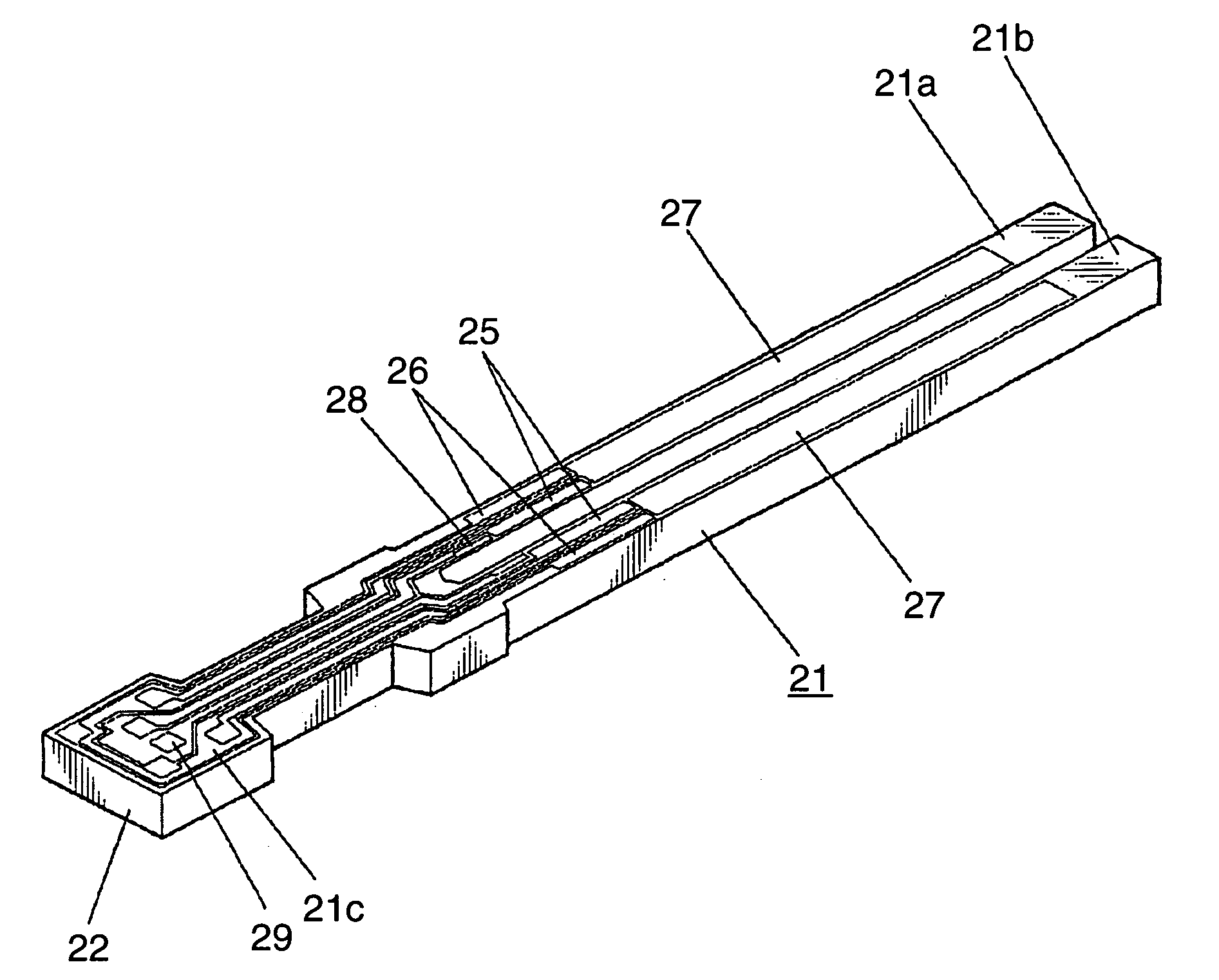
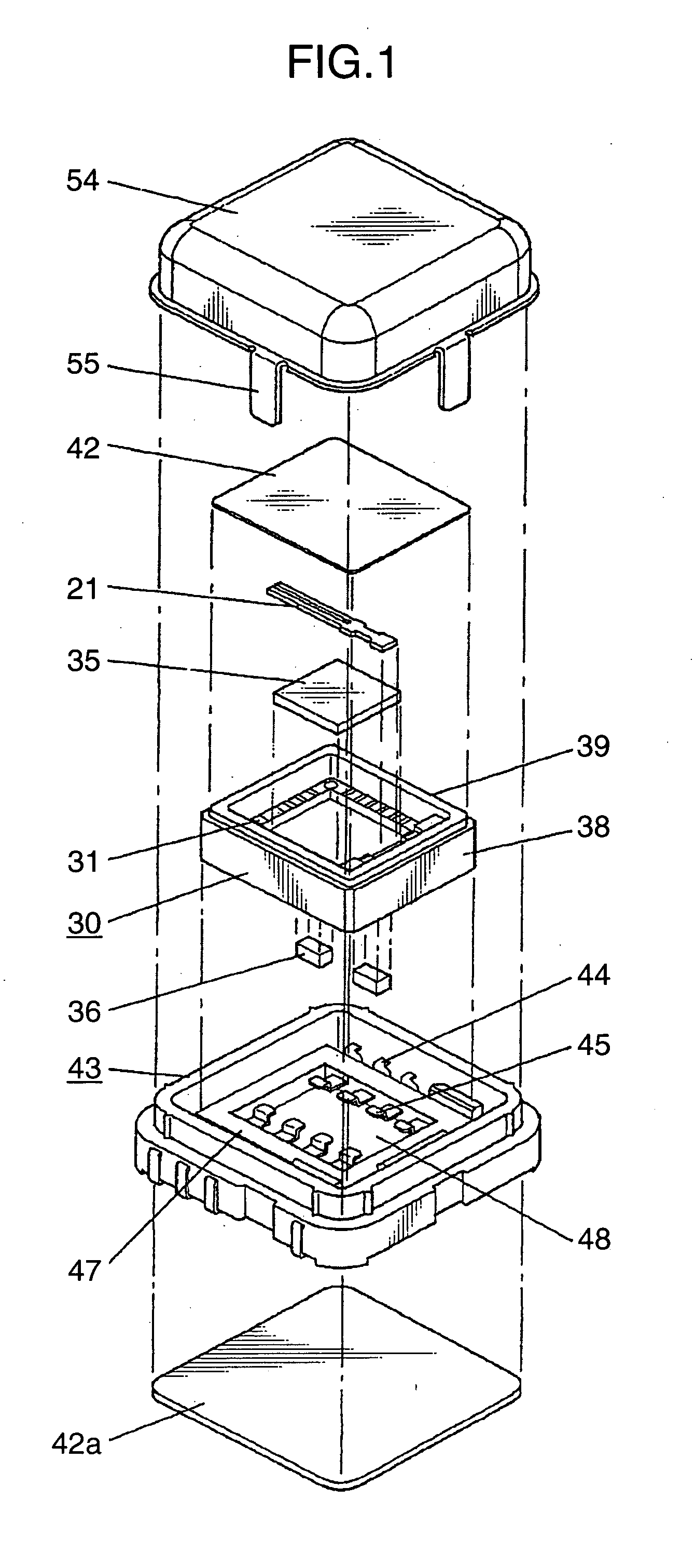
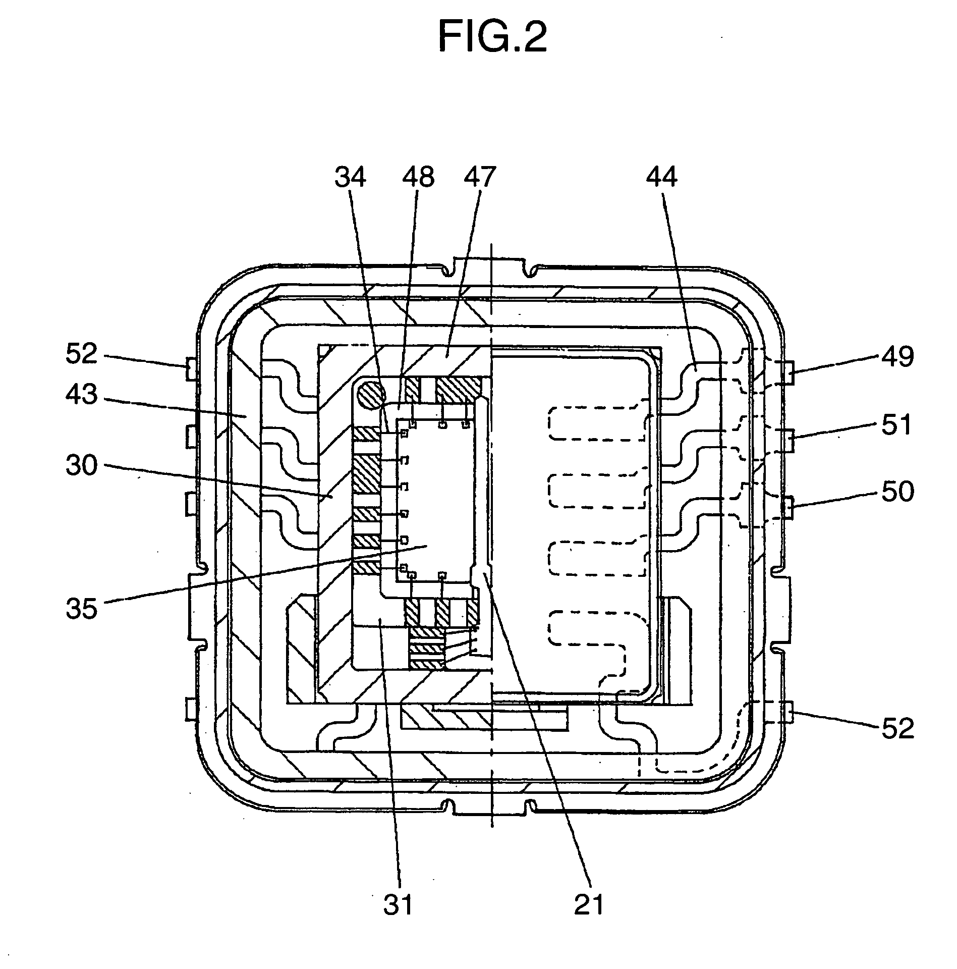
[0031] With reference to the drawings, an embodiment of the present invention will now be described in detail. FIG. 1 is an exploded perspective view showing an angular velocity sensor according to one embodiment of the present invention, and FIG. 2 is a partly sectional top view of the angular velocity sensor. FIG. 3 is a perspective view of a vibration element provided in the angular velocity sensor, and FIG. 4 is a sectional view of a first arm portion of the vibration element provided in the angular velocity sensor. FIG. 5 is a perspective top view of a case provided in the angular velocity sensor, and FIG. 6 is a perspective bottom view of the case provided in the angular velocity sensor. FIG. 7 is a perspective top view of a receiving member provided in the angular velocity sensor, and FIG. 8 is a perspective bottom view of the receiving member provided in the angular velocity sensor. FIG. 9 is a perspective view of a cover provided in the angular velocity sensor.
[0032] As sh...
PUM
 Abstract
Description
Claims
Application Information