

Method of measuring depth of defects in large-scale wind turbine blade using infrared thermography
- Summary
- Abstract
- Description
- Claims
- Application Information
AI Technical Summary
Benefits of technology
Problems solved by technology
Method used
Image

Examples
Embodiment Construction
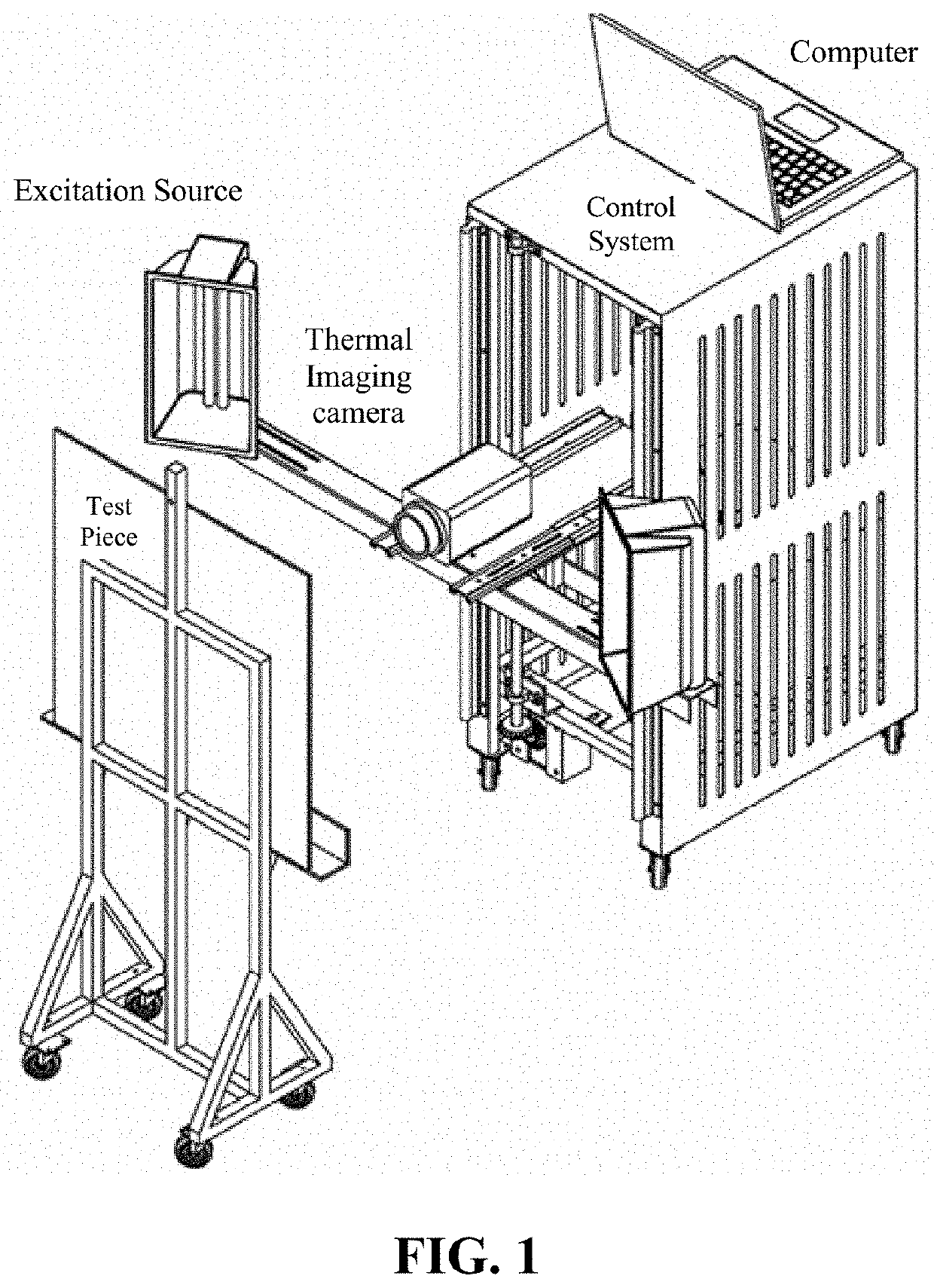
"d_n">[0032]The objects of this embodiment are fragments of a main beam of a certain wind turbine blade, with a total thickness of 30 mm, and a hole in the back cut by a milling machine to generate internal cavity defects with distances of 3 mm, 5 mm, and 7 mm from the surface, respectively. The method for measuring the depth of the internal defects of the blade in this embodiment is further described in detail below in conjunction with the drawings in the examples of the present invention.
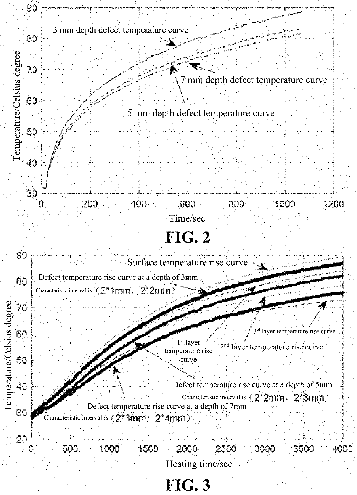
[0033]The theory of the present invention is based on the one-dimensional heat conduction equation excited by a continuous heat source. When a semi-infinite uniform medium is subjected to a continuous heat source parallel to the surface, the heat conduction equation can be expressed as:
∂U∂t=α∂2U∂x2(1)
[0034]in the formula U is a surface temperature, t is time, α is a heat transfer coefficient, x is a depth.
[0035]As shown in FIG. 1, a halogen lamp is used as an irradiation source to continuously hea...
PUM
 Abstract
Description
Claims
Application Information