Electrostatically oscillated device

a technology of electrostatic oscillation and oscillator, which is applied in the direction of generator/motor, snap-action arrangement, instruments, etc., can solve the problems of low sensor efficiency, low drive oscillation efficiency, so as to minimize the increase in the size of the electrostatic oscillator, increase the amplitude of the oscillator, and increase the drive force.

Inactive Publication Date: 2005-09-15
DENSO CORP
View PDF2 Cites 5 Cited by
  • Summary
  • Abstract
  • Description
  • Claims
  • Application Information

AI Technical Summary

Benefits of technology

[0029] The present invention addresses the above disadvantages. Thus, it is an objective of the present invention to provide an electrostatically oscillated device, which has an oscillator and driving electrodes and achieves an increased amplitude of oscillation of the oscillator. It is another objective of the present invention to provide an electrostatically oscillated device, which includes a base, an oscillator and driving electrodes and which provides an appropriately increased drive force for oscillating the oscillator while minimizing an increase in a size of the electrostatically oscillated device.

Problems solved by technology

Thus, the efficiency of the sensor is not high.
Thus, the efficiency of the drive oscillation is not high.
The above disadvantage is not specific to the electrostatically oscillated angular velocity sensor but is commonly encountered when the efficiency of the drive oscillation, i.e., the amplitude of the drive oscillation needs to be increased in the electrostatically oscillated devices, which has the above oscillator and driving electrodes.
However, when the number of the electrode teeth of each driving electrode is simply increased, the size of the board of the sensor is disadvantageously increased.
The above disadvantage is not specific to the electrostatically oscillated angular velocity sensor but is commonly encountered when the drive force needs to be increased in the electrostatically oscillated devices having the oscillator that includes the frame, which surrounds the toothed electrode portion.

Method used


Image

  • Electrostatically oscillated device
  • Electrostatically oscillated device
  • Electrostatically oscillated device

Examples


first embodiment

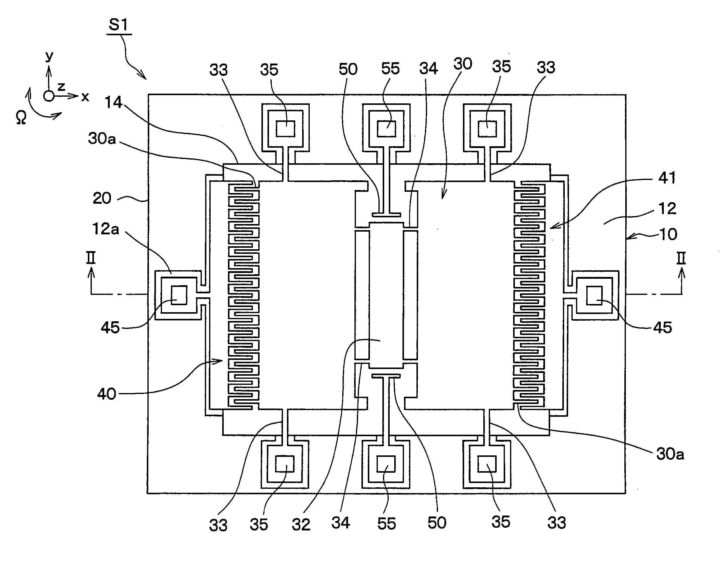
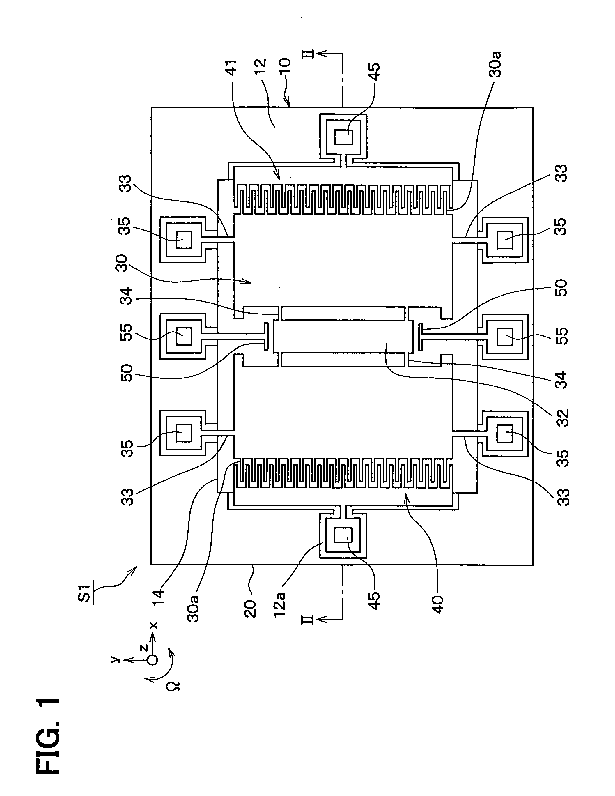
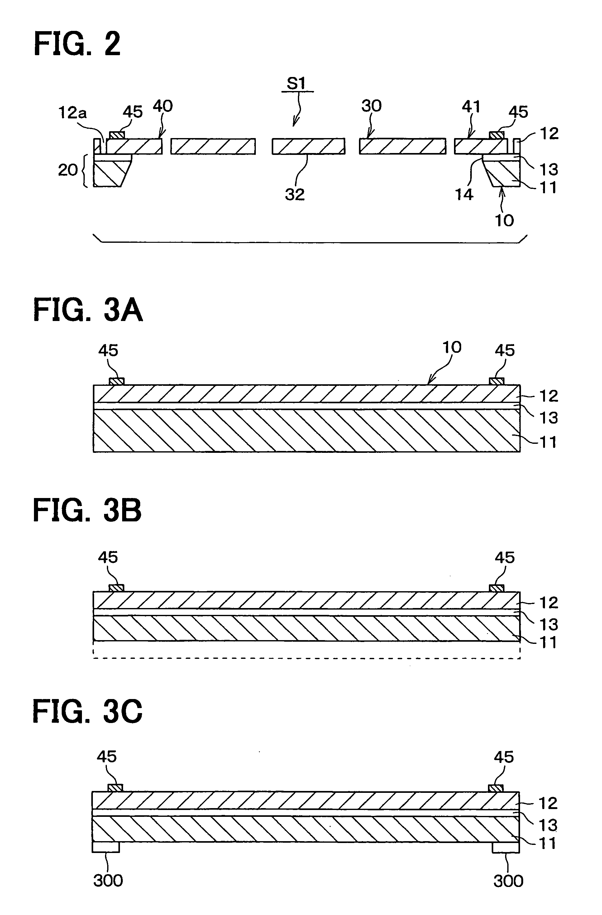
[0044] A first embodiment of the present invention will be described with reference to FIGS. 1 to 5. FIG. 1 is a plan view of an electrostatically oscillated angular velocity sensor S1, which serves as an electrostatically oscillated device, according to the first embodiment of the present invention. FIG. 2 is a cross sectional view taken along line II-II in FIG. 1.

[0045] With reference to FIG. 2, a board of the angular velocity sensor S1 is a silicon-on-insulator (SOI) board 10, which includes first and second silicon plates 11, 12 and an oxide film 13 interposed therebetween.

[0046] Trenches 12a are formed in the second silicon plate 12 to define an oscillator 30, driving electrodes 40, 41, sensing electrodes 50 and bridges 33, 34 in an etching process.

[0047] Furthermore, the first silicon plate 11 and the oxide film 13 are eliminated by etching in a portion of the SOI board 10, which corresponds to the oscillator 30, so that an opening 14 is formed. An outer peripheral portion ...

second embodiment

[0099] A second embodiment of the present invention will be described with reference to the accompanying drawings. FIG. 6 is a schematic plan view of an electrostatically oscillated angular velocity sensor S101, which serves as an electrostatically oscillated device, according to the embodiment of the present invention. FIG. 7 is a cross sectional view taken along line VII-VII in FIG. 6.

[0100] With reference to FIG. 7, a board of the angular velocity sensor S101 is a silicon-on-insulator (SOI) board 310, which includes first and second silicon plates 111, 112 and an oxide film 113 interposed therebetween.

[0101] Trenches 112a are formed on the second silicon plate 112 to define an oscillator 330, driving electrodes 140, 141, sensing electrodes 150 and bridges 133, 134 in an etching process.

[0102] Furthermore, the first silicon plate 111 and the oxide film 113 are eliminated by etching in a portion of the SOI board 310, which corresponds to the oscillator 330, so that an opening 11...


PUM


Abstract

An oscillator is oscillatable in a predetermined direction. First and second driving electrodes are secured to the base and apply an electrostatic force to the oscillator to make drive oscillation of the oscillator in the predetermined direction. At the time of the drive oscillation of the oscillator, a predetermined electric charge is accumulated in the oscillator, and electric charges of opposite polarities are alternately and periodically accumulated in the first and second driving electrodes, respectively, to exert an attractive force between the oscillator and a corresponding one of the first and second driving electrodes and also to exert a repulsive force between the oscillator and the other one of the first and second driving electrodes, and vice versa.

Description

CROSS REFERENCE TO RELATED APPLICATION [0001] This application is based on and incorporates herein by reference Japanese Patent Application No. 2004-70062 filed on Mar. 12, 2004 and Japanese Patent Application No. 2004-70063 filed on Mar. 12, 2004. BACKGROUND OF THE INVENTION [0002] 1. Field of the Invention [0003] The present invention relates to an electrostatically oscillated device, such as an electrostatically oscillated angular velocity sensor or an electrostatically oscillated actuator, which has an oscillator that is oscillated by electrostatic forces. [0004] 2. Description of Related Art [0005] For instance, an electrostatically oscillated angular velocity sensor, which is fabricated by, for example, etching a semiconductor substrate to form a base, an oscillator and driving electrodes for driving the oscillator, has been proposed as the electrostatically oscillated device (see, for example, Japanese Unexamined Patent Publication No. 2003-511684, which corresponds to U.S. P...

Claims


Application Information

Patent Timeline
Patent Type & Authority Applications(United States)
IPC IPC(8): B81B5/00G01C19/5762G01P15/08
CPCG01C19/5762
Inventor HIGUCHI, HIROFUMI
Owner DENSO CORP
Why Eureka
Try Eureka